I just find out that my tube dac output impedance is 250K. If i use 10K attenuator before dcb1, would it be fine?
Let's be clear about this. 250 ohms or 250,000 ohms?
250 ohms, yes, you'll be fine. 250K, then no, and I would be very doubtful it is really 250k...did YOU MEASURE it?
Best,
Anand.
dcb1 was meant to be for universal buffer/volume control/passive preamp (not sure exact name), due to my amplifier will not have any volume control. my original plan was just to use cd player as main source. but dac project came out after dcb1 almost completed.
I have no knowledge on tube yet, this will be my first tubey things. So, how to make it works? which attenuator value should i use?
tube dac -> dcb1 with attenuator -> amplifier
I have no knowledge on tube yet, this will be my first tubey things. So, how to make it works? which attenuator value should i use?
tube dac -> dcb1 with attenuator -> amplifier
Last edited:
Your tube/valve pre-amp output impedance ius almost certainly NOT 250k.
If it were it would be a current source.
It is much more likely that the recommended load impedance should be gretaer than or equal to 250k.
It is very likely that the output impedance is between 500ohms and 2000ohms.
If it were it would be a current source.
It is much more likely that the recommended load impedance should be gretaer than or equal to 250k.
It is very likely that the output impedance is between 500ohms and 2000ohms.
I just find out that my tube dac output impedance is 250K. If i use 10K attenuator before dcb1, would it be fine?
If its 2.5k use 25k pot. If its 1k or less you can even use 10k pot. That DAC having 250k output impedance sounds abnormal. For common cathode It will be equal to the anode load resistor in parallel to the internal resistance Rp when the cathode is capacitor bypassed. Or more if there is no capacitor across its cathode. But not order of magnitude more.
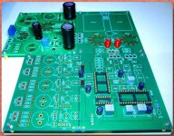
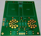
it's not completed yet, 250K for sure. attached picture shows the pcb
Let it play a sinewave when you got it built, say 1kHz. Measure its output with the DMM in AC RMS. Load it with a large value pot wired as rheostat directly across the output. Turn the pot down until the output will show half the previous RMS value. Now detach the pot and measure its last value. That will be the true output impedance.
loading down to half the maximum (open circuit) voltage may draw too much current.
The circuit may enter protection or severe distortion trying to output that much current.
I'd suggest trying to identify the 90% and 80% of maximum output voltage.
Then use some arithmetic to calculate the effective 1kHz output impedance into a "normal" output load.
The circuit may enter protection or severe distortion trying to output that much current.
I'd suggest trying to identify the 90% and 80% of maximum output voltage.
Then use some arithmetic to calculate the effective 1kHz output impedance into a "normal" output load.
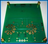
fiuuhh, those procedures seem complicated to me who only have 1 dmm sanwa pc500  I don't have the schematic yet, I'll ask on monday to the seller+designer, but I attached backside picture If anyone can help me to determine actual output impedance. this pcb should be 2 layers. i'm planning to use E88CC (as my friend does who has completed this dac) if it matters on determining output impedance
hopefully i'm not hijacking this thread with different topic, not sure where to ask
I don't have the schematic yet, I'll ask on monday to the seller+designer, but I attached backside picture If anyone can help me to determine actual output impedance. this pcb should be 2 layers. i'm planning to use E88CC (as my friend does who has completed this dac) if it matters on determining output impedancehopefully i'm not hijacking this thread with different topic, not sure where to ask
Attachments

I just see 250K resistors on that board from 0.47uF couplers to ground and it could be Gadut thinks its about output impedance. Output impedance is a series internal figure.
Yes that's my thought and same answer with my friend with highly regarded skill and had completed this dac
Ask the designer about figure Zo or source impedance/output impedance, specifically.
I will do it on monday, I was going to purchase 10K tkd mini reactor nuclear but got confusion before ordering it. Better asked instead of wrong purchase rite
Last edited:
Understanding when and how to use the DCB1 buffer is important to this Thread.
I consider it "ON TOPIC" to discuss what types of Sources suit the DCB1.
However, opening a new Thread to discuss the technical details of that preamp would be a way forward, now that we have identified a possible problem with the proposed interface.
Once we know that answer, we can usefully point Gadut to an appropriate pre-/buffer.
Understanding when and how to use the DCB1 buffer is important to this Thread.
I consider it "ON TOPIC" to discuss what types of Sources suit the DCB1.
However, opening a new Thread to discuss the technical details of that preamp would be a way forward, now that we have identified a possible problem with the proposed interface.
Once we know that answer, we can usefully point Gadut to an appropriate pre-/buffer.
If you can suggest, on which subtopic should I ask? Tubes / Valves or Analog Line Level?
Maybe this will be my question in this topic:
- What will be the range of maximum acceptable source impedance that will work nicely with default dcb1 design?
- If source output impedance is higher than above answer, what can be done to make it work nicely with modified dcb1? Or maybe it will never work
I read in build guide that with 50K pot, "you should make the 220k resistor a 520k one"
Last edited:

So tonight, I tried the Russian teflon caps in the power supply as a replacement for the MKP. While there has been no real "break in" I thought I would report one finding.
These Russian caps are HUGE. So big, I had to install them in the sub-chassis beside the volume control and the input rcas.... not ideal.
I mounted connectors similar to the ones used for input and output signals on the board, with 18 gauge stranded wire -- nothing special. One pin of the connector was cut off to make them fit...... At first, I thought a bigger sound and stage, a bit brighter but more extended bass, but somewhat messy/fuzzy, a bit sibilant, more reverb.
Then I thought: "why not twist the wires to each cap together?" so I did, but loosely. Everything tightened up.
That sounds like confirmation bias. The caps are also not close to broken in, but if there really *is* a difference, one may suggest that the layout/wiring may have something to do with it.....
I wonder if in this case, what folks hear with theseRussian caps actually just wiring issues because they just won't fit. Maybe the same would happen if an MKP was put on the end of the long wires?
Last edited:
- Home
- Source & Line
- Analog Line Level
- Salas hotrodded blue DCB1 build