While you're at it, include one of these: Dact Type 21 Stepped Attenuator Volume 20K FOR Preamp | eBay
They're like $12, made with 1% resistors, and work just fine.
They're like $12, made with 1% resistors, and work just fine.
another vote for TKDbut if you say alps bb is a crap, how would blue velvet be?
anyway the seller keep teasing me with his tkd attenuator
Yes what is that in the middle ? Look like a million.

Balanced DCB1 power supply question
Let's say that I want to design my own balanced PCB version of the DCB1. Would it be sufficient to use just one (salas hot rod) power supply to power both B1 circuits or would it be better to use two power supplies?
When using two supplies, do they need to be very balanced in order to make sure that both channels are like exact copies and the signal get handled the same?
Attachments
Thanks. All clear.
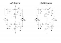
I used sPlan7 for drawing the schematics. The software can't run any simulations, but it's very easy to use. A particular nice feature is that it can make component lists based on the actual schematics.
The schematic drawings are copied from the mesmerize DCB1 schematics, but by drawing them myself I get a better understanding of the schematics than by just looking at them.")
I used sPlan7 for drawing the schematics. The software can't run any simulations, but it's very easy to use. A particular nice feature is that it can make component lists based on the actual schematics.
The schematic drawings are copied from the mesmerize DCB1 schematics, but by drawing them myself I get a better understanding of the schematics than by just looking at them.
Corpius,
can I suggest a change to the mute operation?
Add a second resistor in series with and after the 220r output resistor. This extra resistor could be anywhere from 100r to 1k.
Move the S3 tapping from the output to the junction of the original 220r and the added resistor.
When ON, the switch shorts out the added resistor and the Receiver sees the lone 220r.
When MUTE, the switch connects to Audio Ground and the Source sees [220r+added resistor] as the load.
You could now change the original 220r to 100r, since this is no longer the only load when in MUTE.
Post us your pots review after your tests then.
I have not tested it yet but the more I ask, more people suggest TKD, it's just like your advise previously.
Spent half day just to learn to use new drill, makita 1630 is soo heavy
but it's so fun Attachments
Andrew, I totally missed your suggestion, but what exactly is the benefit from adding more resistance to the MUTE circuit?Corpius,
can I suggest a change to the mute operation?
Add a second resistor in series with and after the 220r output resistor. This extra resistor could be anywhere from 100r to 1k.
Move the S3 tapping from the output to the junction of the original 220r and the added resistor.
When ON, the switch shorts out the added resistor and the Receiver sees the lone 220r.
When MUTE, the switch connects to Audio Ground and the Source sees [220r+added resistor] as the load.
You could now change the original 220r to 100r, since this is no longer the only load when in MUTE.
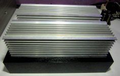
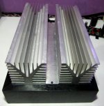
yup, i think that using 2R7 will be a tinny current modeThis one is a real battle tank. You plan just a very little hot-rod current mode I guess.

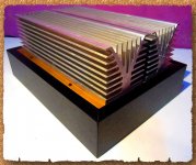
while waiting my toroid package, play with some hand toys during holiday. hand saw aluminium plate to direct mount irfp's for the best heat transfer, and spray with golden paint. several holes are unused and not so rectangular saw result due to not so skillful me
Attachments
Last edited:
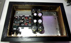
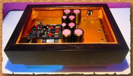
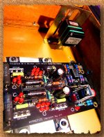
I've just been populating the DCB1 Black using the parts Tea-Bag sent me and the build guide wushuliu on Audio Circle put together. There are a few things I would like someone to clarify if possible please.
(1) Matched 2SK170BL - they came as 2 pairs along with the board which shoom kindly gave me. 1 pair were labelled 6.91/982 the other were labelled 6.92/883.
The build guide I used only concentrated on getting them orientated the right way. I fitted one matched pair one way round and the other pair the other way. I now see that near the start of this thread, Salas mentions that they should be placed in a particular order. Are mine close matched enough for this not to be an issue?
(2) I had 2 sets of large 6.5W wire wound resistors, 5 ohm and 10 ohm, I fitted the 10 ohm resistors. Will I need to heatsink the IRFP240/9240 to the enclosure or will a set of clip on heatsinks be enough to dissipate the heat at this power rating if I use a well ventilated enclosure?
(3) my transformer is 2 x 12v 50va (2.08 amp) I have not tested it yet but with my mains voltage it will probably output closer to 14v. Will this transformer be ok in this case or will I have to reduce the boards power consumption?
(4) I did not receive any 1R resistors, can I fit wire jumpers with this configuration?
Cheers
Davy
1. If well matched the order is no big deal, you will revisit that only if your mV offset will be more than the averagely reported here.
2. Clip on will also do with 10R setting if of substantial size, not like those smallish ones we usually see LM317s on. Still, sinking on the enclosure is zero $ and looks elegant too.
3. 5V DC vin-vout at weaker mains hours is best to be a target. The reg will work even with 1V dif but its CCS will be compromised. There are Schottky diodes to use as well that can save some rectification losses due to their lower Vf, but they should be at least 60V reverse spec in your case.
4. Jumpers are fine. Those 1R serve a test point function for general reg uses irrelevant to your purpose.
You are welcome
Salas
- Home
- Source & Line
- Analog Line Level
- Salas hotrodded blue DCB1 build