Gentlemen,
just a comment regarding silver wire for signal path...I don't think it is such a good idea for the DCB1. It is alrady very revealing and transparent, and silver, in my experience, contributes even more to this transparency reducing the upper bass region and emphasizing the mid/high freq somehow. This can be a wanted effect to balance out a somewhat dark sounding system, but in this case...I would prefer copper. I had good results with litz wire, where the single thin wires are isolated. I think cardas has someting like this; I even tried some very thin HF-Litz with silk isolation drilled together with brilliant results. Like shown here:TheLitzPeople.com - Litz Wire, Round Litz, Stranded Litz..
I have a friend who built the DCB1 and was disappointed, because it sounded thin and uninspiring. I asked how he built it, and of course he used pure silver for signal wire...
As Salas already pointed out, it is a question of synergy and the right mix.
cheers, and
happy building
Juergen
Ah, something else...in my system the DCB1 sounded better with 15V AC transformer and with 3,9 ohms current resistor for around 450mA, I can't go higher unfortunately. Beefier and more colours in my book. And I use an EMI filter, the DCB1 has almost no limit in high frequency and lets it all pass.
Running 10R resistors will be moderate hot rod? I thought this was somewhat of a mid level and that you can push it even further... With the 10R still lots of heat?
In a long ago post, Salas defined the "levels" as:
Stage 0 = circa 75-85mA Ecological and cool. Smart car territory, the twin 47R 1W marked on the Blue and no or mini sinks will do.
Stage 1 = circa 200mA. Boosted enough, all purpose, some logical sinks. Standard Blue HR, Golf GTI territory. 4W dissipation per rail. 10R 5W.
Stage 2 = circa 600mA. Increased grip and pull back, Porsche stuff. 12W dissipation per rail. Sinks like for a 30W class A/B amp. 3R3 5W.
Stage 3 = circa 2A. No holds sense, Enzo feel. 40W dissipation per rail. F5 size sinks & Tx. 1R 12W.
")
I did some measurments today with my temporary external PSU build.

Its an old tranny I found in the closit (5 of them actually), one 10 mF per rail and some 2 A 30 mH chokes intended for filament cleanup.

I hooked the scope up on first C, aka after the chassie bolted rectifiers.

Around 530 mV ripple
Then on the board mounted C, after chokes:

Around 12,6 mV ripple
Then on Vout

Like 2,5 mV ripple.
Vin is around 20.5 V and Vout almost spot on 10 V. If Im gonna hotrod it some more (10R atm) Im gonna need dual trafos.
/Staffan
Its an old tranny I found in the closit (5 of them actually), one 10 mF per rail and some 2 A 30 mH chokes intended for filament cleanup.
I hooked the scope up on first C, aka after the chassie bolted rectifiers.
Around 530 mV ripple
Then on the board mounted C, after chokes:
Around 12,6 mV ripple
Then on Vout
Like 2,5 mV ripple.
Vin is around 20.5 V and Vout almost spot on 10 V. If Im gonna hotrod it some more (10R atm) Im gonna need dual trafos.
/Staffan

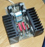
the heatsinks must have their fins orientated so that the fins are vertical and that air can flow from bottom to top.
Well, that is the most effective, but if they are big enough it doesnt matter that much. Heres mine standing fins down on the desk over an hour.

30,6 Celsius
/Staffan
Last edited:
Its intended for serving both 2 channel music and multi channel movie. I havent decided on setup finally yet, right now Im leaning on 5.1 with side channels balanced. I think the real build will use 2 trafos so I can turn on the balanced stereo and multichannel channels separately.
Got me some used lightspeeds, 4 stereo boards but the optos doesnt seem to match that well. Thats next step.
/Staffan
Got me some used lightspeeds, 4 stereo boards but the optos doesnt seem to match that well. Thats next step.
/Staffan
Hi Salas
From your post below - do you (or anyone) have a link to the mini survey regarding BOM parts?
Here's another interesting thread on a DCB1 build and discussion on upgrading components.
Howlin's Pre build Blog - Page 3
From your post below - do you (or anyone) have a link to the mini survey regarding BOM parts?
Here's another interesting thread on a DCB1 build and discussion on upgrading components.
Howlin's Pre build Blog - Page 3
The red Wimas in the particular type and value came out best in a mini survey we run among some users in the past to recommend in the BOM. Best among proven and widely available industrial options in manageable sizes and prices though. Having an ultra pot you may be interested in some Teflon mix was my drift. About the black box Wima I have no direct comparison experience to convey.
It was some posts somewhere in the DCB1 threads not a specific thread.
P.S. The link shows some nicely recorded build cost subjective comparisons. Can't beat the British on homing in to best value. The 5leds bypass position wasn't under attention in that case. Some wrong description of the Mez though. Thanks for that info.
P.S. The link shows some nicely recorded build cost subjective comparisons. Can't beat the British on homing in to best value. The 5leds bypass position wasn't under attention in that case. Some wrong description of the Mez though. Thanks for that info.
100 Ohm buffer resistors Y split to start with.
Apologies for the naive question... does this effectively give the DCB1 dual/parallel outputs?
Thanks,
Ryan
I'm also looking to do 1 pair R/L of RCA inputs to 2 pairs of R/L of RCA outputs after the PCB1. I'm running my PCB1 as just a buffer having no vol control. I was going to run the RCA in to the DCB1 and then run two pairs of outputs
I'm going to run on output R/L to a tube amp with 180K input impedance and then the other output R/L to a plate amp (28K input impedance) running a sub.
The 100R resistors run on the ouput.. Is this for situations like I have where the two amps i'm driving are so far apart on input impedance?
For the Right channel as an example. Would I run the + output of a R channel to two 100 R resistors and then one resistor to the 1 Right RCA + output and then the next resistor to the other 1 Right RCA + output?
I
- Home
- Source & Line
- Analog Line Level
- Salas hotrodded blue DCB1 build