I'm 99% positive I've got it all put together correctly. Like I said 99% but I always look for MY mistakes first. I'm going to replace cap and see what happens. I do remember all leds lit up the one side went dark and then my son said "Hey Dad! It's smoking!" he thinks I'm crazy for doing this as he thinks everything computer is where it's at.
I'll let you know what happens.
I'll let you know what happens.
But you say all lit up. Maybe a Mosfet gone instantly? Are they OK for types and pcb sides? Inspect their writing on their cases carefully, they stamp it lightly some times or use laser.
Fuse it low and try again. All Mosfets should show a bit lower than 4V between their G, S pins or there about.
Fuse it low and try again. All Mosfets should show a bit lower than 4V between their G, S pins or there about.
All as it should be. maybe bad cap? truth is stranger than fiction...
Don't know how bad a cap can come to blow instantly, I have heard some stories but never occured to me so dodgy. Take out a pair, the bad and its opposite side mate, run it on two cylinders to see.
After a few months of having Tea-Bag's kit on the side collecting dust, I finally decided it s time to get something more than a plain pot for my system. (I really don t like the passive approach with my setup)
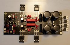
The parts were soldered as proposed on the thread and the guides. The leds were measured at 5,61V and 9,35V per side.
Unfortunately my DMM's mA measurement is fubar and I am a bit lazy to make any resistor/voltage based setup, so I will have to trust Tea-Bag's matching kind-of blindly (marked as 8,3x mA)...
The kit came with 10R resistors so 1st level hotrod (for now).

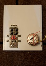
The fets and the diodes will be soldered after the bottom plate is drilled and the components insulated and screwed in place (here they are layed around randomly).
The bottom will be a 40cm x 40cm aluminum plate 5mm thick and with around 3cms bent on each side to allow for easier and sturdier side mounting.

The target is to get it eventually to 2nd tier or a bit more, depending on how well the aluminum plate will dissipate the heat (Any comments on how feasible is that without any extra side heatsinks?).
I am too tired to play with mains now, so I will have to do the final drilling soldering and testing tomorrow.
The test transformer will be a Hammond 2x12V @ 120VA. The hammonds run a bit on the low side of voltages also, so I will have to get a proper 15V one eventually.
The parts were soldered as proposed on the thread and the guides. The leds were measured at 5,61V and 9,35V per side.
Unfortunately my DMM's mA measurement is fubar and I am a bit lazy to make any resistor/voltage based setup, so I will have to trust Tea-Bag's matching kind-of blindly (marked as 8,3x mA)...
The kit came with 10R resistors so 1st level hotrod (for now).
The fets and the diodes will be soldered after the bottom plate is drilled and the components insulated and screwed in place (here they are layed around randomly).
The bottom will be a 40cm x 40cm aluminum plate 5mm thick and with around 3cms bent on each side to allow for easier and sturdier side mounting.
The target is to get it eventually to 2nd tier or a bit more, depending on how well the aluminum plate will dissipate the heat (Any comments on how feasible is that without any extra side heatsinks?).
I am too tired to play with mains now, so I will have to do the final drilling soldering and testing tomorrow.
The test transformer will be a Hammond 2x12V @ 120VA. The hammonds run a bit on the low side of voltages also, so I will have to get a proper 15V one eventually.
Attachments
The other option that I really like is this
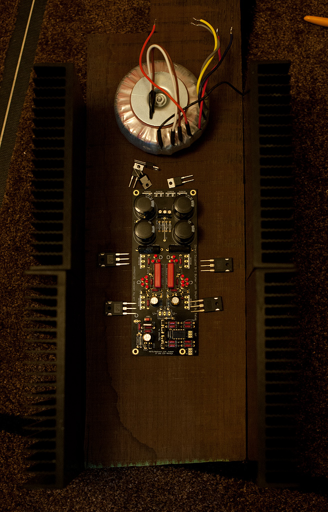
The wood is wenge which I really like for that kind of work. It is heavy and dense which makes for an excellent vibration dissipation platform, and it is really beautiful as well.
The heatsinks are the ones used on the 4U HiFi 2000 dissipante series, and based on the F5 analogy they should be enough for tier 3 hotrodding..
The only issue with this approach is that the board's width is small, and in order to have the fets on the heatsinks the chasis will have to be narrow. The fets are also close together which means that they will have to be attached on the edge of the heatsinks, which might affect how the heat spreads to take advantage of the entire area of the metal. The narrow design also means less space to allow better isolation of the transformer and to keep the wires away from each other. It will require some careful design on how it should be layed out. Especially since I was planning to include a lightspeed in it.
Do you think those heatsinks would be enough to hold 2 fets each on tier 3 hotrodding? Perhaps it would be a solution to attach the board on the side on the heatsinks instead of on the wood.
Attachments

Last edited:
What is the C/W for each of those?
According to their site it is 0,31 C°/W
So tier 3 would be 40W per rail or 80 watts total? Which means 0,31x80 = 24,8 above ambient temperature?
Which would mean roughly 50 degs celcius more or less if we consider the rating accurate and a mean ambient temp of 20-25 degs
Last edited:
1A per rail is 20W per side for DCB1. Derate the sinks by 30% since Mosfets will be hot spots driving the metal surface, when any sinks are supposing full surface heating when characterized.
Hmmm on this post you are specifying 40W per rail for 1R @12W
http://www.diyaudio.com/forums/anal...hotrodded-blue-dcb1-build-38.html#post2312521
Anyway, 20W per side means 10W per mosfet (and per heatsink).
30% derating on the heatsinks translates to 1deg Celsius per watt more or less, or 10 degs above ambient for 10Watts.
It should be really comfy? Or am I noobishly missing something?
Link says 2A 40W. It computes OK for my 1A 20W example.
30% would make them 0.31C/W (if honestly rated) circa 0.4C/W. Means just 8C above ambient for 20W on such a sink. IRFPs used are 0.83C/W RθJC. If you got 40C building up in enclosed box, each sink will be 48C. 1C/W thermal resistance silicone pads mount will give 58C on MOSFET cases. 10W each will give +8.3C to the chips inside. Below 70C or about if its a hot day or the box inside cooks more than assumed. Still cruising speed for 150C core melting point parts like these.
30% would make them 0.31C/W (if honestly rated) circa 0.4C/W. Means just 8C above ambient for 20W on such a sink. IRFPs used are 0.83C/W RθJC. If you got 40C building up in enclosed box, each sink will be 48C. 1C/W thermal resistance silicone pads mount will give 58C on MOSFET cases. 10W each will give +8.3C to the chips inside. Below 70C or about if its a hot day or the box inside cooks more than assumed. Still cruising speed for 150C core melting point parts like these.
- Home
- Source & Line
- Analog Line Level
- Salas hotrodded blue DCB1 build