Amazing!
will you never set up a buying Group for this project?
If so, I am interested.
Regards.
That would depend on whether or not this will work without individualized adjustments to the code in the PIC to compensate for unmatched LDRs.
One solution to this problem could be to buy matched pairs from UDailey so that custom programming is not required -- this design requires six LDRs because each shunt leg uses two LDRs (LEDs in series, resistors in parallel) to reach 25 ohms at somewhere between 5 and 11 milliamps of current. (One goal of this project is to provide a wide range of attenuation without ever coming close to the 20ma maximum current specification.)
Another possibility is that it may turn out that by purchasing maybe twenty or thirty unmatched LDRs at a few dollars apiece, you could match your own. The board has a precision LDR testing facility built in to make this possible.
This afternoon I had just a little while to tinker with the circuit.
1. I discovered that there is a completely reversed and better way to use the adjustment pots I've incorporated into the design which may permit the board to be used without custom programming the PIC for every unique set of LDR devices. (Needs further experimenting)
2. I added some software tweaks that greatly improved the speed at which changes in resistance could be achieved by turning the control pot, and the LED now reliably indicates when all resistors are stable at the value where the potentiometer has commanded them to be (panel-mounted LED on when stable, off/blinking when any LDR is adjusting).
3. I had a stereo pair of LDRs working as commanded by the potentiometer -- from 25 ohms at the low end to 100K ohms at the high end (moving in opposite directions as a standard pot would work), and completely reliably. The 100K is now possible because of my changing the use of the adjustment pots as I described above.
The changes I made a couple of days ago seem to have opened up the design in a big way, things are starting to work smoothly.
Today I did some experimenting and learned that I can eliminate five trimmer pots from my design and add just two fixed resistors for a considerably simplified board. The multi-turn trim pots were taking a lot of space, so this will help a lot where space on the board is concerned.
I also started to characterize the LDRs I have on hand. I have 44 devices, and I tested them all to determine what current was required to produce a 50 ohm resistance. For my design, all shunt LDRs must produce 50 ohms or less at 10ma or less. LDRs which do not meet this requirement will become series LDRs unless they are simply outside of manufacturer’s specification. I was pretty pleased with what I discovered: of the 44 units, only eleven would not hit 50 ohms at 10ma or less, and quite a few of them would hit 50 ohms at 8ma or less. The eleven that would not hit 50 ohms at 10ma, will work just fine as series LDRs.
The LDRs in my design will draw a total of less than 20ma for both channels at maximum or minimum attenuation or anything in between. Clearly the LM317T I was planning on is not needed -- it can be replaced by an LM317L.
An interesting aside – at one point today I had control of an LDR at 3.5 mega ohms, and I thought that was pretty amazing. It turns out that good control up to about 100k ohms is pretty straightforward.
Here is the breakdown of the current draw of the LDRs at 50 ohms resistance:
3ma -- 1
4ma -- 3
5ma -- 4
6ma -- 5
7ma -- 4
8ma -- 9
9ma -- 5
10ma -- 2
>10ma – 11
Thank you! I think I've just more-or-less finished the basic control code -- now fast and glitch-free control from 50 ohms up to around 100K ohms per device and reliable control of two devices for each shunt resistor to achieve 25 ohm minimum resistance at less than 10ma per device.
First emulation will be a standard log pot, range of 25~10K ohms for 52db attenuation; have just started working with a collaborator to define the parameters and math required for the PIC.
First emulation will be a standard log pot, range of 25~10K ohms for 52db attenuation; have just started working with a collaborator to define the parameters and math required for the PIC.
Last edited:
After a frustrating day hunting for a problem that turned out to be nothing more than a wire that had come disconnected, things are shaping up. I am now able to deliver a 10K pot with a minimum of 54dB of attenuation (with minimum shunt and series resistances of 25 ohms, although I've had the shunt resistance as low as 17 ohms) with no device drawing more than 10ma of current. By extending the series side resistance to 25K ohms, 60dB of attenuation is possible with output impedance remaining low.
Made final choices on resistor values and capacitors. I wanted to use polyester low leakage caps in the control paths, but I need larger values than are available that way so have had to accept tantalum. Tantalums have fairly high leakage, which is a nuisance but unavoidable.
By selecting LDR devices from the 44 that I now have on hand, I could build this "pot" with no device drawing more than 5ma at minimum or maximum attenuation or anything in between. That means that LDR devices should never be in dangers of changing characteristic due to high current. The Silonex LDR is rated at 20ma, and my LDRs will always be operating at 50% of rated in worst case and usually much less.
With improved precision in measuring, I find that the current draw of my 44 devices are spread more evenly than I first thought. To produce a 50 ohm resistance (the value required to achieve a 25 ohm resistance with two paralleled devices) the current draw is spread like this:
ma - # devices
3 - 2
4 - 3
5 - 7
6 - 6
7 - 8
8 - 6
9 - 2
10 - 3
> 10 - 7
Yesterday, I had three LDRs running with their LEDs in series and the output resistors in parallel. It appears that this is absolutely no problem, just a matter of changing the values on a couple of minor components per channel.
Using the rule of 50 ohms at 10ma or less per device, that means that the shunt resistor in this arrangement running at no more than 10ma can be either 25 ohms (for two LDRs per shunt) or 16 ohms (for three LDRs). The 25 ohm and 16 ohm values translate to 52dB and 56dB of attenuation respectively for a 10K pot. I wonder if that's enough difference for anyone to care? You would need a pretty high-gain system to need 56dB of attenuation, wouldn't you?
By increasing maximum series resistance from 10K ohms to 17K ohms (completely doable) I could brag on 60dB of attenuation.
I haven't posted in a while, but I've been making some progress.
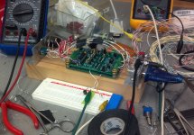
The attached photo shows the current design on a 2.5" x 3.8" board (it's pretty messy because I have changed and replaced a lot of components along the way).
The design can be controlled by either pots or by button presses, and has selectable modes: Stereo (Volume & Balance), Mono (two independent channels), and Calibration (for initial calibration, changing the pot value, creating independent R1 or R2 response curves, or periodic recalibration).
The design will deliver very good channel-to-channel accuracy with LDRs that are selected only to meet minimum standards, not matched. I have tested the design with one, two, and three LDRs paralleled in the shunt legs which allow 17 ohm shunt values even at a very conservative maximum drive current of 11ma. A 10K pot with 54db of attenuation is entirely doable using current values that don't even come close to affecting the long-term stability of the LDRs.
By adding a little external wiring for calibration, it's looking very good for a board that could be totally assembled and calibrated in a wide variety of configurations by the end user without involving any programming skills.
Attachments
I'm also quite curious to see how this level of current control works out too and applaud you continuing work.
I've been hoping to get some free time to check out the idea of using the T pad attenuators, rather than the usual L-pad, to see if it makes any difference, but as the 3 different Lightspeeds I have are all working perfectly (George's, Uriah's and Allan's, plus those little sneaky variable resistors of Uriah's!) there isn't much incentive to attempt to re-invent the wheel, (particularly as I'm not very good at it!)
I've been hoping to get some free time to check out the idea of using the T pad attenuators, rather than the usual L-pad, to see if it makes any difference, but as the 3 different Lightspeeds I have are all working perfectly (George's, Uriah's and Allan's, plus those little sneaky variable resistors of Uriah's!) there isn't much incentive to attempt to re-invent the wheel, (particularly as I'm not very good at it!)
I'm also quite curious to see how this level of current control works out too and applaud you continuing work.
I've been hoping to get some free time to check out the idea of using the T pad attenuators, rather than the usual L-pad, to see if it makes any difference, but as the 3 different Lightspeeds I have are all working perfectly (George's, Uriah's and Allan's, plus those little sneaky variable resistors of Uriah's!) there isn't much incentive to attempt to re-invent the wheel, (particularly as I'm not very good at it!)
James, thank you for the kind comments. I just looked back over this thread and realized I've been fooling around with LDRs for three and a half years now! Certainly there have been long periods of total inactivity in that time, but still I've put in some hours on this, and over the period I've tried a lot of various configurations and have given them some thought, and certainly reached a number of dead ends and some conclusions.
I have been trying to get people to look at the technical aspects of the LDR on another thread that is dedicated to the type of boards you have built, and sometimes the effort turned into a good conversation and sometimes it turned into accusations of trying to hijack the thread and/or hijack potential customers. Yet my vision is nothing like George's board or Uriah's board and I know nothing of a board made by "Allan." I simply was interested in getting people thinking and talking about the reality of what an LDR is and how it works. By the way, could you give me a link to Allan's board which I have never heard of? I would like to see what it's about.
My concept is entirely different from George's or Uriah's implementation, although it is similar to Uriah's in one key concept -- the ability to independently select different values for the R1 and R2 sides of a potentiometer section to allow for special circumstances like an overall system with excessive gain, or a requirement for special consideration for the source impedance or the amplifier impedance.
George's board is elegantly simple and easily implemented except for the requirement to hand-select individual LDR devices. George does, in fact, recommend that all four LDR devices in a stereo potentiometer be quad matched, which makes the matching even more challenging than finding two matched pairs to do the job. George says that power supply regulation is, after a point, not important. The Lightspeed does use a voltage-regulated circuit.
Uriah, on the other hand, from what I am given to understand, seems to espouse using two sets of matched-pair LDRs per board rather than a matched quad set, but also believes in a very pure power supply with lots of capacitance smoothing. I have never seen a diagram of his circuit so I cannot say what the circuit philosophy is so know nothing of its strengths or weaknesses from the perspective of what I think I have learned about LDRs.
Some folks on the other thread seem to think that I'm trying to pit voltage controlled systems against current controlled systems. I'm not, because there is a place for both types. The voltage-based circuit is easily implemented and no doubt sounds wonderful. The PIC-controlled current-based circuit serves an entirely different purpose and has tradeoffs. The tradeoff is, in exchange for much greater complexity and expense, you get predictability and repeatability and flexibility.
I seem to be one of only a few people who are interested both in analog audio electronics and in digital electronics. I could see how they would work together and when combined, produce the best of both worlds -- on the audio resistor circuit side a device that is just as simple and pure as George's Lightspeed, and on the driver LED side a circuit that is far more consistent and repeatable and absolutely inaudible to the listener.
My design goals are:
1. Easing of the LDR matching requirement. Pretest only for minimum resistance and maximum resistance at predetermined minimum and maximum current. Pass/fail test with at least 60% yield from randomly selected LDRs.
2. Close tracking of the logarithmic response curve.
3. Very close tracking between channels.
4. Stability over time and temperature variation.
5. Consistency of tracking to make multi-channel control possible (5.1, 7.1, etc).
6. User-adjustable pot value from 5K to 50K to optimize for most solid state or vacuum tube systems.
7. Make the building, calibration, and modification of response curves to custom values easy enough and repeatable enough to allow DIY construction by hobbyists and customization to exactly match the needs of the specific system.
I started my latest configuration running yesterday morning, holding LDRs at 10K ohms at room temperature +/- 20 ohms. I put an ice cube against one LDR and the resistance changed a mere 10 ohms average at 10K ohms. I was thrilled, and announced the fact on another thread and that was not received well.
 BTW, this circuit has been running continuously for a day and the resistance is still exactly where it was when I started the circuit yesterday.
 Over the past several months I've really put some effort into the firmware and have made good progress. Also about the same time realized that I should revisit an IC that I had looked at three years ago and rejected because it would not deliver the performance I thought (then) that I needed. I've looked at it again with new criteria and find that it works -- which means that I can do away with my SMT-only ICs and reduce the price of components by about $12 per board.
So, I'm headed in the right direction and I see no technical issues that will be a show-stopper, but only time will tell.
With regard to your intererest in a "T" filter, I did look at it at the very beginning of my research and decided that it was more effort than it was worth in an audio environment. It is, however, the correct configuration for a an LDR-based input-switching circuit, so if you're interested in that, I believe you're on the right track. I'm delighted that you're experimenting with LDRs, and I wish more people would get interested because I'm sure the learning curve would get steeper the more people are involved.
Last edited:
I'm also quite curious to see how this level of current control works out too and applaud you continuing work.
I've been hoping to get some free time to check out the idea of using the T pad attenuators, rather than the usual L-pad, to see if it makes any difference, but as the 3 different Lightspeeds I have are all working perfectly (George's, Uriah's and Allan's, plus those little sneaky variable resistors of Uriah's!) there isn't much incentive to attempt to re-invent the wheel, (particularly as I'm not very good at it!)
James, I did a search and found Alan's LDR website, so disregard my request for a link.
I have been a bit absent from doing anything with the Vol Pots, apart from Uriah's little variable resistor 'things' so I went back and started re-reading your thread and so far just about #47 - saw your note about reducing the design from T network to L pad
I'll add a curious thing about those weird T-Network 'things' - in the studio of 'a few years ago', we all tended to follow the lead of the best equipment available if the budget allowed, plus a dose of common sense to accompany the usual compromises -
Well, I was trying to optomise a passive Xover using some Coral compression drivers on some tractrix midrange horns and found that the type of attenuator pad made a quite significant difference to the sound (forward and backward impedance loading), and this had to be significantly better than the current driver/horn combinations at that time (mid 80s) and required an attenuation between 10 to 16dB in 1dB steps - pretty simple really with rotary switch, etc but a real PIA to wire the Isotan resistance wire and attach the contact points and so on.
Anyway, it worked really well and achieved the better performance particularly in regard to a reduction in dynamic compression (something not really worried about back then, on the last days of analogue systems)
I wonder if something similar could maybe have some good results altho the situation is vastly different.
Now, back to your post ...
I'm absolutely amazed that you can actually control a consistent 10k impedance (20R = +/- 0.2%, yes?) for starters, and to be able to maintain this in the face of chilling the devices and still get anything like a lowly 10 ohms variation is astonishing (to me, anyway) - if my arithmetic is correct, this represents a temperature variation of 0.1% on a device that's pretty ordinary impedance behaviour to start with!
That's quite an achievement in itself, and I 'take my hat off to you' for that alone.
I don't know why the guys on George's thread aren't clamouring for the circuit and knowledge of how you achieved this - I'm sure it won't be long coming.
I remember Tom (Gootee was working on something along these lines awhile back and ran into trouble controlling the very low current control required - will read up and see if he achieved a good result.
Another guy called Paul Hynes, known for excellent power supplies, also did a slightly different Lightspeed - I regret not getting a kit/finished unit from him.
When I first tried George's basic LightSoeed, I was using an F3 amp and it unfortunately had an inputZ of less than 9kR and the Lightspeed unit just didn't like this particular load all that much and I got a loss of bass control - couldn't increase the input Z, so added a simple buffer and no problems.
With Uriah's, it was a different story in that I could/can adjust the impedaces at will and it was interesting in just how much the different loading altered the sound created by the impedance variations
Allan's Warpspeed was a different 'kettle of fish' again - it came in a pre-assembled kit and merely required the LDRs to be attached and it showed a remarkable increase in transparency over much wider impedance loads from my F5 (100kR), to the F3 (9kR), to the 'crappy switcher amp' (3k5R) - very amazing characteristic.
As it had a simple battery supply, this got sent all over town here in a number of different systems and quite a few guys missed out when Alan stopped supplying both the kits and the finished units.
I recently got a couple of Uriah's little variable resistor kits and bloody smart little gadgets indeed - at present playing around with subbing them into the cd player as an alternative to the I/V resistor - tried them in the F5 amp but the signal voltages are far too high, unfortunately.
Will read the thread and maybe add some better informed comments, but good on you, this is quite an achievement already.
I'm absolutely amazed that you can actually control a consistent 10k impedance (20R = +/- 0.2%, yes?) for starters, and to be able to maintain this in the face of chilling the devices and still get anything like a lowly 10 ohms variation is astonishing (to me, anyway) - if my arithmetic is correct, this represents a temperature variation of 0.1% on a device that's pretty ordinary impedance behaviour to start with!
That's quite an achievement in itself, and I 'take my hat off to you' for that alone.
James, your post made me think about this some more and I need to qualify my original statement because there is a caveat here.
My circuit can run in two modes -- one mode holds resistance constant regardless of outside influences and adjusts current to correct a changing resistance. The other mode holds current exactly constant at a set point and ignores resistance.
In order to maintain resistance in the face of large changes in temperature, the circuit must be running in "hold resistance" mode. In that mode, there is virtually no change of resistance regardless of temperature. That is the caveat.
In constant current mode, there is a change of resistance when the LDR is chilled with an ice cube. Nevertheless, considering the extreme temperature change of an ice cube held against the LDR, the resistance change isn't great.
I do believe that the major resistance change that others have noted is caused by temperature changes within the LED causing it to conduct more or less current and thus changing the light output. This phenomenon is well documented but ignored by the voltage-control folks. A current controlled circuit will keep current constant regardless of LED temperature and thus resistance at the output will remain more stable.
I'll have to see what the real-world impact is when I get a new circuit card built (having recently done a major redesign of drive circuitry, I need a new prototype for full-blown testing).
Last edited:
Subscribed!
Hello, Merlin, welcome!
+1 - great thread - good luck with your design.
Thank you!
I had a weird thought when catching up on the past posts, particularly from Tom's mention about the variation in the impedance at both the input and the output over the whole range of attenuation (low volume to high volume, I mean!) as per post #182.
We all have assumed that our controlling pot has to be either a log or linear impedance curve, right?
Well, what if we reconfigure this as a completely different curve that will change the impedances of the series and shunt devices independently to produce more linear input and output impedances across the volume range?
A bit along the lines of Uriah's LighterNote but making the curves of the main control pot 'non-standard'.
It is quite possible to alter the curves on commercial pots in various ways (ie Rod Ervine's esp website) or to build some individually calibrated stepped pot curves that aren't log or linear ....
Or, am I just 'blowing smoke' again on this New years day?!
- Status
- This old topic is closed. If you want to reopen this topic, contact a moderator using the "Report Post" button.
- Home
- Source & Line
- Analog Line Level
- A precision LED/LDR-based Attenuator