You mean the company whose IR spectrometer I used for qualitative organic chemistry made a typo?
VTL5C3 1.5 ohms at 40mA.
Yup, that sounds like the one where the graph shows 1.5K ohms instead of 1.5 ohms and 1.5K is correct. I actually got an order of parts before I discovered the error. Allied gave me a full refund and told me to throw the parts away.
Well, the minimum resistance value is important in the max attenuation range. With 40 ohms, with a 5K Zo, the math says I only get 42dB attenuation maximum. At a lower Zo, a slightly greater attenuation is possible.
Is there a PerkinElmer device that reaches, or almost reaches, 40 ohms? I did not find one when I went looking . . .
At the minimum attenuation end, you only need a much greater number, so it's not a problem.
With reagard to the dual-LDR devices, the dual LDR shares a common wire (3-wire device) and that kinda limits its usefulness.
Well, I could have sworn that they had lots of them that went below 100 Ohms. But looking at the data plots again I see only two. One of those goes to 50 Ohms but it is undesirable otherwise. And I could have sworn that the VTL5C2 models that I measured went down to 40 Ohms or even less. But that was a long time ago and the Perkin Elmer data plot that I'm looking at right now shows between 100 and 200 Ohms minimum for the VTL5C2.
So I'm sorry. What I said was apparently INCORRECT.
But I wonder if there would be any advantage to putting them in parallel with fixed resistances, to get a lower minimum resistance. Their dynamic ranges do go from 65 dB to 112 dB. And they do seem to have a larger selection of other characteristics. You might also consider paralleling the Silonex devices with fixed resistors, if it happens to be advantageous.
Cheers,
Tom
Well, I've thought of that, but first I want to try a 'purist' approach that puts LDRs only in the signal path. I've looked at wandering resistances at high values, I think it's partly due to actual variation in resistance, and partly due to the difficulty of measuring large resistance values accurately. I still think I can make a .5~42dB attenuator with a fairly constant Z of 5K, and that should be pretty good for many applications.
I've ordered some boards which will be here Friday. After I get one up and running and able to program it, we'll see how complicated the software has to get. It'll be fairly easy to set two diffierent current ranges for the series and shunt LDRs and have them respond in opposite directions as you change the input. Right off the bat, there will be advantages over the straight log pot technique due to being able to program two different resistance ranges to respond to a single input range; it remains to be seen how much math will eventually be required to make the native Silonex curves play correctly with smooth, consistent, attenuation and relatively constant Z.
Here are two other ideas (edit: the second one is probably more attractive):
1.) I wonder if you should try to use feedback control loops, so that basically "nothing would matter" regarding the actual LDR curves, and you could maybe greatly reduce the overall complexity of your scheme in that regard.
Essentially, if it were able to be implemented, your system could simply tell the LDR control systems what resistances were needed and the feedback systems would automagically adjust the LDRs' control currents to get them there.
To implement it, you would only need to be able to continuously measure the resistances, to provide the feedback signals. Then you just subtract the signals that correspond to the resistances from the command signals that correspond to the desired resistances to produce a signal that changes the current. When the resistances are what your system told them to be, the command signals (literally) automatically stop changing and the currents and resistances are exactly where you told them to be.
To do that, you would have to be able to sense current through and voltage across the LDRs' resistive elements, without the audio circuit being affected significantly (i.e. basically not at all). But that should be able to be done by using extremely high input impedance voltage sensors (maybe just the right type of FET-input opamps?).
Once you could sense the voltage across a very-low-value current-sense resistor and across the LDR's resistance, you'd almost have it.
The only other thing that might be a minor problem, at first, would probably be setting the time constant for your resulting command signals to be slow-enough for the LDRs to respond, so that you wouldn't over-correct at first, and also wouldn't potentially oscillate the (LDRs') control current.
-----
2.) An entirely different type of scheme that is also conceptually simple (and also requires no additional analog circuitry) would be to have a "calibration/learning" mode, in which the system would automatically test each LDR and store its entire resistance-vs-current curve in a table, so that from then on it could just do a table lookup to set the current to exactly what was needed for any desired resistance. And Voila!
(I would probably code this type of table-lookup routine so that it would always interpolate between data points, if necessary. Then, potentially, your software or firmware could piecewise-linearize each curve, within certain error margins you had set, when it built each table, possibly storing far fewer data points, but it would still all work within specs.)
Cheers,
Tom
Here are two other ideas (edit: the second one is probably more attractive):
1.) I wonder if you should try to use feedback control loops, so that basically "nothing would matter" regarding the actual LDR curves, and you could maybe greatly reduce the overall complexity of your scheme in that regard.
-----
2.) An entirely different type of scheme that is also conceptually simple (and also requires no additional analog circuitry) would be to have a "calibration/learning" mode, in which the system would automatically test each LDR and store its entire resistance-vs-current curve in a table, so that from then on it could just do a table lookup to set the current to exactly what was needed for any desired resistance. And Voila!
Tom
For me, I would view the first as beyond my abilities to implement. It would introduce major technical challenges including a slew of additional analog parts and I can't imagine how you would extract resistance information from music. Not that it can't be done, I just don't know how to do it.
The second is what I am actually doing. I don't need any analog chips to make it happen -- aside from the PIC, just one capacitor, three resistors (one for current limiting), and one mosfet per LED. That's a pretty minimal parts count. Everything else on the board is for voltage regulation, volume control, and option selection.
If I were going into the matched LDR biz, I would just use a programmable current source to establish the control law for each device, and bin them. (Now where did I put my HP6177C?)
The devil is in the details . . .
Have you found a programmable current source which, in a single chip, can
1) control current from 20ma to .0005ma?
2) control four (up to eight) different current loads simultaneously?
3) interpret two separate inputs and apply them differently to different outputs?
4) offer programmable options to offer flexible inputs?
If yes to all, please tell me and I'll have a look. If not, I'll stick with my single-chip PIC solution . . .
")
BTW The whole point in my project is to entirely do away with 'matched' LDRs -- I want to use LDRs off-the-shelf that require no matching other than to insure they meet minimum specifications.
20mA to 500nA is a range of 92dB -- at 500nA you might find that the radiation from the PIC is going to modulate the diode current!
There's an interesting tale on the Analog Devices website, of a designer who was driving himself nuts with a strange modulation of a low noise circuit -- turns out that the radiation from a fluorescent bulb was impinging upon one of the diodes. It's not medical instrumentation with life-threatening applications we're discussing here, but interesting to note.
There's an interesting tale on the Analog Devices website, of a designer who was driving himself nuts with a strange modulation of a low noise circuit -- turns out that the radiation from a fluorescent bulb was impinging upon one of the diodes. It's not medical instrumentation with life-threatening applications we're discussing here, but interesting to note.
20mA to 500nA is a range of 92dB -- at 500nA you might find that the radiation from the PIC is going to modulate the diode current!
There's an interesting tale on the Analog Devices website, of a designer who was driving himself nuts with a strange modulation of a low noise circuit -- turns out that the radiation from a fluorescent bulb was impinging upon one of the diodes. It's not medical instrumentation with life-threatening applications we're discussing here, but interesting to note.
If it does, it'll be at 32MHz!
20mA to 500nA is a range of 92dB -- at 500nA you might find that the radiation from the PIC is going to modulate the diode current!
When I converted to new electronic ballast for the fluorescent fixtures in my workshop, my portable FM radio picked up nothing but intense static. I had to install an outside antenna to be able to listen to the radio again.
For me, I would view the first as beyond my abilities to implement. It would introduce major technical challenges including a slew of additional analog parts and I can't imagine how you would extract resistance information from music. Not that it can't be done, I just don't know how to do it.
The second is what I am actually doing. I don't need any analog chips to make it happen -- aside from the PIC, just one capacitor, three resistors (one for current limiting), and one mosfet per LED. That's a pretty minimal parts count. Everything else on the board is for voltage regulation, volume control, and option selection.
Sounds good. So, never mind!
It feels kind of nice when I come up with an idea and it's the one that's already been selected for a design. <smile>
Regarding the first option I sputtered about (feedback control system), it definitely would require additional (analog) hardware (not to mention possible additional D-to-A conversion stuff). And for someone unfamiliar with both analog and feedback control system design it might present too much additional design risk and workload. But it probably would have been able to work well, and would have eliminated some programming and some memory usage, and might have been fun to try for a one-off (if someone like me was doing it, at least). However, as I implied, I think that the way that you're doing it would be the better of the two, even for someone who was proficient at everything needed for doing it either way (unless a purely analog solution was desirable, for some reason, which might then make it the only option for not having to match LDRs).
(Just for the sake of academic discussion: ) Regarding measuring the resistances of the LDR elements while audio was playing, it would mostly have been a matter of measuring the "voltage across" and the "current through", simultaneously, and then dividing V/I = R. The instantaneous V and I, although they change as the audio signal changes, should still always have the ratio R, IF you assume that R is a pure resistance. A little low-pass filtering or averaging of a short stream of V/I calculations would probably have been able to remove any "real world" artifacts/effects (such as non-ideal-R, and/or not-quite-simultaneous measurements of V and I).
Anyway, never mind.
Cheers,
Tom
Last edited:
2.) An entirely different type of scheme that is also conceptually simple (and also requires no additional analog circuitry) would be to have a "calibration/learning" mode, in which the system would automatically test each LDR and store its entire resistance-vs-current curve in a table, so that from then on it could just do a table lookup to set the current to exactly what was needed for any desired resistance. And Voila!
Tom
This is what I'm building at the moment. An Arduino with some DACs and ADCs over I2S. For calibration, I steer the LEDs with current from a DAC, and I sense the resistance from the LDR with an ADC. For sure I need some opamps and relais just for the calibration. It's more parts then the straight "George" design. Some advantages are: no matching, impedance controllable, presets etc. And most of all: fun to implement.
Biggest issue I have is the terrible response curve of the Sylonex. I already designed an exponentiel amp between the DAC and the LED to compensate, that makes it more or less reasonable. I still need to finish this, it's no easy as the transistors I need are not straightforward.
How is this working? Can you clarify? That could solve the terrible response of the Sylonex as well, avoiding the exponential amp.P.S. I also designed a circuit that can completely linearize the normally more like logarithmic resistance vs control current response curve of any LDR. Unfortunately, it requires a second LDR that is an exact match to the one being linearized, in order to precisely linearize it.
Tom
Joost
This is what I'm building at the moment. An Arduino with some DACs and ADCs over I2S. For calibration, I steer the LEDs with current from a DAC, and I sense the resistance from the LDR with an ADC. For sure I need some opamps and relais just for the calibration. It's more parts then the straight "George" design. Some advantages are: no matching, impedance controllable, presets etc. And most of all: fun to implement.
Biggest issue I have is the terrible response curve of the Sylonex. I already designed an exponentiel amp between the DAC and the LED to compensate, that makes it more or less reasonable. I still need to finish this, it's no easy as the transistors I need are not straightforward.
How is this working? Can you clarify? That could solve the terrible response of the Sylonex as well, avoiding the exponential amp.
Joost
Cool!
Well, it was more-or-less just an exercise in design and simulation, because in order to get a perfectly-linear response curve, it requires a second perfectly-matched LDR to create a feedback loop.
The matched "feedback" LDR's diode is in series with the diode of the LDR to be controlled. A precision constant current source pushes curent through a resistor and then the feedback LDR's resistance cell and then through a current-sense resistor to ground. The differential voltage across the feedback LDR's resistance cell is fed into an instrumentation amplifier. That amp's output and the control voltage input are fed into another differential instrumentation amplifier. That "error" amp's output is RF filtered and feeds into a proportional/integral controller (optional) and all AC components are removed (but not with a low-pass filter because it would be far too slow), which feeds a precision voltage-controlled current source. The current source feeds into the LDRs' diodes, which are connected to a negative voltage source at the other end.
It was able to slew at about 10K Ohms per millisecond and had overshoot of less than 1% for large R targets, with a settling time of 5 or 10 ms, and had steady-state error of less than 0.1% for R > 1K Ohms. And, of course, within the stated error, the resistance of the LDR was exactly linearly related (i.e. proportional to) the control voltage that was applied. The version I am looking at now, in LTspice, would set the LDR's resistance to anything from 1K to 1 Meg for a control voltage of 5 mV to 5 V. That one was using VTL5C2 LDRs, with the response times of the LDRs also modeled. But other types of LDRs could easily be used.
But, I haven't built one. So I don't know how much good it might do with two un-matched LDRs. But I imagine that it might be a big improvement.
-----
By the way, I think there is an easy way to make an "inverse function" of something by putting the something into the feedback loop of an opamp. So you might be able to make a "curve cancellation" amplifier that is used to drive the LDR diode current. The LDRs wouldn't be matched. But it would be a lot closer to linearization than nothing.
-----
For an exponential amplifier, it's probably much easier to use an opamp-based circuit.
-----
I wonder if you could dispense with the calibration mode by using "pilot tones" that are outside of the audio range to measure the LDR resistance continuously, in near real time.
OR, just measure the resistance continuously in near real time using the audio signal and a current-sense resistor, and continuously measure the voltage across the current-sense resistor and the voltage across the LDR's resistance cell and divide and scale to get a continuous LDR resistance measurement. Then implement an automatic feedback control system loop (maybe with a differential integrator and low-pass filtering) to make the resistance follow a control voltage input. I already described that approach, somewhat, I guess. The key would probably be to use differential voltage measurement circuits, to measure the voltages across the current sense resistor and the LDR's R, that would be somewhat like the ones used in active FET probe circuits, i.e. with input impedances so high that they couldn't possibly affect the audio.
The beauty of the automatic feedback control system approach is that any particular control voltage value would make any and all (un-matched) LDRs go to the same resistance (within the LDRs' basic current/resistance range and with a certain tolerance/error, of course). It could even be used to automatically control series and parallel LDRs, just as easily, which might open up some new possibilities for dynamic range, etc.
Cheers,
Tom
Why did I put an exponential amp while doing what you describe is much more logical, and I have some extra optocouplers hanging around. Quite easy to do I guess:By the way, I think there is an easy way to make an "inverse function" of something by putting the something into the feedback loop of an opamp. So you might be able to make a "curve cancellation" amplifier that is used to drive the LDR diode current. The LDRs wouldn't be matched. But it would be a lot closer to linearization than nothing.
Tom
I already have an opamp that converts voltage to current between the DAC and a LED.
Put a 2nd opto-LED in series with the one for audio.
Add a current source in series with the 2nd LDR.
Feed the voltage over the LDR as feedback to the opamp driving the LEDs.
Only issue is that the voltage over the LDR is wrong way around. I need to think how to solve this, but this is a minor thing.Put a 2nd opto-LED in series with the one for audio.
Add a current source in series with the 2nd LDR.
Feed the voltage over the LDR as feedback to the opamp driving the LEDs.
Again, why didn't I think about this before??? Thanks a lot for the tip.
I will not match the optocouplers. The only reason to use this feedbackloop, is to have a more or less lineair link between the output of the DAC and the LDR-resistance. I'll do the calibration to have a perfect lineair link between the digital values and the resistance by software. But I will couple both optos thermically, that way the feedback loop will cancel most of the temperature drift. That solves another concern I had.
The solution to link a pilot measurement parallel to audio makes me afraid. I want to have the audio as clean as possible. Adding anything can only worsen things as any signal can influence amps behind. And I go 100% DC to the poweramp. I don't want additional condensors or whatever filters. I think the optocouplers are stable enough, and I can do a calibration whenever I want. It will take some hours to measure the full range for every resistor, but it can run in the night.
Joost
Tom wrote a model for the Perkin Elmer --
Here's a general discussion of modelling a "Voltage Controlled Resistor" -- an LDR is a "Current Controlled Resistor" so you have to rearrange things a wee bit:
Voltage-Controlled Resistor
Here's a general discussion of modelling a "Voltage Controlled Resistor" -- an LDR is a "Current Controlled Resistor" so you have to rearrange things a wee bit:
Voltage-Controlled Resistor
Does anyone have Spice files for the Silonex NSL-32SR2?
I'm thinking that the individual devices have such loose tolerances that it's not feasible to have a Spice definition?
Back in 2008, I put the resistance and current values for it (from the datasheet) into my general LDR model that was originally used for the VTL5C2 device. But you might have to add the time constants, etc. And of course the model doesn't take into account any of the variations for temperature, or variations between different devices, etc. But I guess it's still pretty useful.
I just posted the following (text) files, for LTspice:
NSL-32SR2.ASC (LTspice/pspice model)
nsl-32sr2.asy (LTspice component assembly for use on schematics)
NSL32PLOT.asc (test circuit that plots R vs I curve like datasheet)
NSL32PLOT.plt (plot settings file used automatically by test circuit)
Download them:
http://www.fullnet.com/~tomg/nsl32sr2.zip
which is a Winzip file containing the four files listed above.
Cheers,
Tom
Last edited:
I just posted the following (text) files, for LTspice:
NSL-32SR2.ASC (LTspice/pspice model)
nsl-32sr2.asy (LTspice component assembly for use on schematics)
NSL32PLOT.asc (test circuit that plots R vs I curve like datasheet)
NSL32PLOT.plt (plot settings file used automatically by test circuit)
Download them:
http://www.fullnet.com/~tomg/nsl32sr2.zip
which is a Winzip file containing the four files listed above.
Cheers,
Tom
Thanks very much, I've downloaded them and will have a look at them. My own experience is, and I think I've read others say, that the published curve is pretty optimistic.
The company that produces my PIC of choice is about a year behind in publishing Spice models for their newest chips and that's a major problem for getting my project into a model.
Now where did I publish that chart affirming Silonex' numbers...Thanks very much, I've downloaded them and will have a look at them. My own experience is, and I think I've read others say, that the published curve is pretty optimistic.
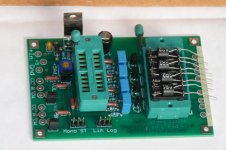
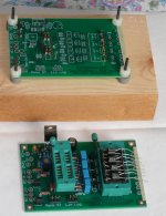
First L pad prototype board received and stuffed, and bed-of-nails board partially prepared (not yet wired).
As usual, as soon as I ordered the boards, I found a way to make a major improvement which required the rewiring of four IC pins, so this board is working with some rewires on the bottom.
Bed of nails is first try, now know that you should have at least two pins in a row to lend stability. Next board will have two rows of six and a third row of three times three pins, should be very stable and reliable.
Unless I run into major coding problems, should be able to get both the calibration code and operation code on one chip. That means potentially recalibrating in the field if you also have the bed of nails board.
The LDRs all reside on one header which can go into a socket for easy replacement or maintenance, but the LDR resistor wires are not cut off -- they extend out and will go into pads on the board for direct soldering to the input/output wires.
Had to put the IC ZIF on top of a socket to get some height because several components are too close to the IC to allow the ZIF socket to rest on the board.
Not visible are the pads that the LDR wires go into. Also taped over the labels on the input and output pads because they are mislabelled.
Attachments
Last edited:
- Status
- This old topic is closed. If you want to reopen this topic, contact a moderator using the "Report Post" button.
- Home
- Source & Line
- Analog Line Level
- A precision LED/LDR-based Attenuator