Here is a rather accurate graph of the Silonex LDR response.
Current is divided into 460 equal steps along one axis, and the Silonex resistance is charted in relation to the current delivered. Resistance range shown is 40 ohms to 85K ohms, approximate. Pretty spectacular corner.
Second chart is LOG scale
Not sure I understand your plots. Maybe I'm just looking at them wrong. They appear to show resistance increasing with current. See jackinnj's plot in post # 19. You should have high resistance at low current and low resistance at high current. If the current increases to the right along the horizontal axis, then the resistance on the vertical axis should slope from upper left to lower right. The plots you posted look more like the voltage versus current of just the LED portion, which would be exponential.
Here is a nice paper about them, although it happens to refer to the Perkin Elmer / Vactec VACTROL types, which are similar to the Siliconix models in how they operate:
http://denethor.wlu.ca/pc300/optoisolators/analogoptoisolatorintroduction.pdf
Last edited:
Here is a paper from Perkin Elmer with Audio Application Notes for Analog Optical Isolators, such as the vactrols and the Silonex devices:
http://www.perkinelmer.co.uk/CMSResources/Images/44-3429APP_AnalogOpticalIsolatorsAudioApps.pdf (144k)
And here is the Perkin Elmer Vactrols homepage:
Analog Optoisolators and Optocouplers|PerkinElmer
http://www.perkinelmer.co.uk/CMSResources/Images/44-3429APP_AnalogOpticalIsolatorsAudioApps.pdf (144k)
And here is the Perkin Elmer Vactrols homepage:
Analog Optoisolators and Optocouplers|PerkinElmer
I think wapo is showing the response of the shunt LDR (in series/shunt attenuator setting)...the series LDR will follow jackinnj attached plot which is the more natural way of showing its response as an LDR starts high and lowers as power to it is controlled.
I was not paying any attention to which direction the values go, only charting the relationship between my control input vs LDR resistance. The y axis represents a change in voltage drop in equal steps across a resistor in series with the LDR. In this first iteration I could do 450 equal steps, but that's not good enough -- many steps at the low end of the LDR range and the LDR resistance doesn't change much, and then not enough toward the top where the LDR resistance changes rapidly with minute changes in current.
With one or two additional passive components I think I can increase the current control step count to above 1000 which will give me finer resolution of the LDR resistance range. Also, I may rearrange the order of components in the limit resistor-LDR-control resistance string We'll see.
Not sure I understand your plots. Maybe I'm just looking at them wrong. They appear to show resistance increasing with current.
No -- LDR resistance increasing as series resistance to the LED is increased, which in effect reduces current through the LED. My goal is precise control of the current through the LED. I can already do the precise control, but in not enough steps to cover with precision the dynamic range of 40 ohms to 350K ohms (which I want in order to do a T attenuator with1/2 dB steps starting at 1/2 dB attenuation.
Last edited:
You could look at some different LDR models.
Sorry, what is meant by "models?"
Sorry, what is meant by "models?"
"Different models" means either different part numbers from the same manufacturer or different manufacturer and part numbers.
Each part numer has different characteristics. Some other type/model/part number might have a slope that is much easier for you to control.
For example, look at the first of the two PDF files that I gave links for, to see the ranges of characteristics that are available in one manufacturer's LDR types.
Last edited:
"Different models" means either different part numbers from the same manufacturer or different manufacturer and part numbers.
Oh, I thought you were referring to different theoretical implementations or something like that . . .
As long as you have the "control law" you can use the equations to determine how any implementation will work.
That is not the problem that I am interested in at this point.
Currently, the individual devices themselves are not manufactured consistently enough to implement a "control law" that does not involve the nasty job of hand-matching components for two channels and very great difficulty in matching more than two channels at a time. This is the problem I'm interested in -- to make it possible to implement a multi-channel system with consistent attenuation response across channels without hand-matching individual devices. At this point, I'm mostly interested in the variation between parts and how to deal with that variation, not in designing a working system.
Update -
For the moment, I've switched from a T pad to an L pad style attenuator, and initial testing of the control suggests that I can achieve a .25~42dB attenuator with a constant Z of 5K with good accuracy with unmatched devices. Not as good as the T attenuator, but it should be adequate.
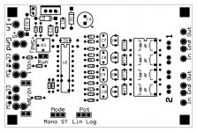
Switching to an L pad allows me to use 4 devices (comfortably loaded on a 24-pin header without bending wires) for a two-channel board that is configurable as a dual mono or stereo (volume + balance) instead of the eight devices for the T pad.
Design permits through-hole potentiometers on-board, or wired separately. Jumpers to allow multiple boards operating in 'mono' mode to be connected to a master volume control for surround sound or sound board applications, providing the lack-of-matched-sets concept works out OK.
I'm planning to use a socket for the 24 pin header, and extend the LDR resistor wires to solder directly to pads. That will allow flexibility in removing the header if needed for servicing, and yet ensure a fully soldered connection between the LDR resistors and the input/output pads.
Added pads to permit installation of capacitors (tantalum) across LEDs if desired.
A week of company this week, won't be doing anything for a while . . .
For the moment, I've switched from a T pad to an L pad style attenuator, and initial testing of the control suggests that I can achieve a .25~42dB attenuator with a constant Z of 5K with good accuracy with unmatched devices. Not as good as the T attenuator, but it should be adequate.
Switching to an L pad allows me to use 4 devices (comfortably loaded on a 24-pin header without bending wires) for a two-channel board that is configurable as a dual mono or stereo (volume + balance) instead of the eight devices for the T pad.
Design permits through-hole potentiometers on-board, or wired separately. Jumpers to allow multiple boards operating in 'mono' mode to be connected to a master volume control for surround sound or sound board applications, providing the lack-of-matched-sets concept works out OK.
I'm planning to use a socket for the 24 pin header, and extend the LDR resistor wires to solder directly to pads. That will allow flexibility in removing the header if needed for servicing, and yet ensure a fully soldered connection between the LDR resistors and the input/output pads.
Added pads to permit installation of capacitors (tantalum) across LEDs if desired.
A week of company this week, won't be doing anything for a while . . .
Attachments
I am seriously intrigued by the perkin elmer audio applications document. That is some cool stuff, although mechanically delicate to work with (soldering, mounting leads, etc.).
Though I could never build something like this, I love reading innovative audio science.
Why could you not build using an LDR? The wiring is delicate, but that is easily managed if you put the LDRs on a DIP header. I myself use a 24 pin header to hold four devices very comfortably.
If you want something now, kits are available in the Lightspeed thread. My system is somewhat more complex and will not be finished for a while.
I am seriously intrigued by the perkin elmer audio applications document. That is some cool stuff, although mechanically delicate to work with (soldering, mounting leads, etc.).
Though I could never build something like this, I love reading innovative audio science.
BTW, using the same document you're talking about, consider using the Silonex device that is sold by udailey which has lower minimum resistance than the PerkinElmer device and is therefore more appropriate to this application.
Actually, Perkin Elmer has a large family of LDR device types that, the last time I checked, out-range the limited product line of Silonex in every way. But once you get down to tens of Ohms, why does it matter, for this application? They also make dual-LDR devices that look interesting.
Actually, Perkin Elmer has a large family of LDR device types that, the last time I checked, out-range the limited product line of Silonex in every way. But once you get down to tens of Ohms, why does it matter, for this application? They also make dual-LDR devices that look interesting.
Well, the minimum resistance value is important in the max attenuation range. With 40 ohms, with a 5K Zo, the math says I only get 42dB attenuation maximum. At a lower Zo, a slightly greater attenuation is possible.
Is there a PerkinElmer device that reaches, or almost reaches, 40 ohms? I did not find one when I went looking . . .
At the minimum attenuation end, you only need a much greater number, so it's not a problem.
With reagard to the dual-LDR devices, the dual LDR shares a common wire (3-wire device) and that kinda limits its usefulness.
Is there a PerkinElmer device that reaches, or almost reaches, 40 ohms? I did not find one when I went looking . . .
.
If you look back through the Lightspeed Attenuator thread from what one our members found when he emailed them, you'll see this was a misprint by Perkin Elmer they forgot to add a zero and should have read 400ohms. They don't make anything that is suitable with low enough resistance. And the dual one would be nice but it's also way to high resistance.
Cheers George
That could have been me. I found their documentation had a typo in it, and you had to look at the graph and compare it to the text list of parameters. And it was the "K" that was left off -- so the actual bottom was about 1.2K ohms rather than 1.2 ohms as published.
If you look back through the Lightspeed Attenuator thread from what one our members found when he emailed them, you'll see this was a misprint by Perkin Elmer they forgot to add a zero and should have read 400ohms. They don't make anything that is suitable with low enough resistance. And the dual one would be nice but it's also way to high resistance.
Cheers George
You mean the company whose IR spectrometer I used for qualitative organic chemistry made a typo?
VTL5C3 1.5 ohms at 40mA.
- Status
- This old topic is closed. If you want to reopen this topic, contact a moderator using the "Report Post" button.
- Home
- Source & Line
- Analog Line Level
- A precision LED/LDR-based Attenuator