Thanks for the insights and probable challenges ahead.
Reading your topic I realise getting a high control resolution is the tricky part hence my 2-stage design. If even 50 dB should be sufficient I can work with 25 dB per stage.
My programming would not be simpler to achieve the needed restance ratio but to reach 25 dB with a "close to ideal curve" is much easier than 50 dB.
Aah, there's plenty of good reasoning in your connector design method - as usual, I put my blinkers on and just wrote out my version of reality - sorry about that.
I can't see any problems about adding another half inch or so to the size of the boards - might make it easier to assemble & mount, too
Hi Oystein,
It's generally not a good idea to connect 2 attenuators in series as the output impedance of the first one will make the required input impedance of the second one a rather unrealistic proposition, unless you include an impedance buffer in between - this is where the more complicated attenuators 'come to the fore', so to speak (it's fascinating what comes off my fingers when half awake!)
I have a 'thing' for the delightful "T network" but it has it's own limitations hence, the more complicated "H", Pi, D(delta), etc, and then balanced this one and balanced that - there's a whole world of attenuators but have mostly fallen into disuse in hifi - still ever present in transmission line work, high freq, etc so the information is available
For anyone facing a situation that does require an impedance buffer, a guy called 'keantoken' has developed a 'new one' called the Kuartotron and includes links to the Calvin buffer too - an alternative to the well known dcB1 buffer (Hypnotize project)
Awhile ago, George reluctantly offered a circuit of a valve buffer design that apparently has a very neutral sound signature - it's also on my list of projects
All the best - these design considerations & things make that Suduko seem tame, IMO!
It's generally not a good idea to connect 2 attenuators in series as the output impedance of the first one will make the required input impedance of the second one a rather unrealistic proposition, unless you include an impedance buffer in between - this is where the more complicated attenuators 'come to the fore', so to speak (it's fascinating what comes off my fingers when half awake!)
You are correct when using 2 volume controls (potmeters or similar) in series.
My design consist of 2 (inverting) amplification stages where throug varying the feedback resistors (LDR 2 and 4) the ampfification (in fact attenuation) works as volume control..
The first stage has a low output impedance which is feeding the second stage through LDR 3.
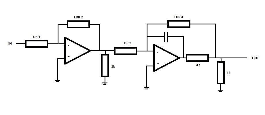
To put values in perspective: LDR 1 and 3 could be 47k and LDR 2 and 4 could be 1k at max attenuation an increased to maybe 10-20k for high volume.
But before we start hijacking this topic please respond in my topic where I introduced my design.
Topic: http://www.diyaudio.com/forums/analog-line-level/267600-pre-amp-2-stages-adjustable-gain.html
Two stage attenuation is possible.
It is adopted in the switching Aikido attenuator. Three-Switch Stepped Attenuators & Aikido SE Amplifiers
It is sort of done with professional amplifiers, where the main vol coltrol is at the operator's hand and there are subsequent "presettable" sensitivity pots on the inputs of the power amps.
That last prompts me to suggest a Home compatible 2stage attenuator.
A normal range attenuator, either using a switcher or a wiper type for the hour to hour volume adjustments. Then a second switched attenuator for quiet, medium and loud that is preset to suit the mood of the hour.
The main vol control could have a 30dB or 50dB range and a mute option, the presettable could have options for 0dB, -20dB, -40dB.
That combination allows continuous vol control covering a total range from -0dB to -90dB and more depending on the mute.
As mentioned by James
The Aikido got the impedances a bit wrong. I have reported a couple of times how to solve that and get very good stage to stage loading without adding a buffer in between.It's generally not a good idea to connect 2 attenuators in series as the output impedance of the first one will make the required input impedance of the second one a rather unrealistic proposition, unless you include an impedance buffer in between
Last edited:
the recommended Rs:Rin is usually 1:10
some will say never use less than 1:5.
I often try to achieve 1:20
An Rs of 200ohms with a 1:20 ratio requires an Rin = 200*20 = 4k ohms.
The first stage of the Aikido could be set to 4k and this would comply with 1:20
The maximum output impedance of an attenuator is ¼(Rs+Rvol pot) = ¼(200+4000) = 1050r
For a 1:20 ratio from first stage to second stage the Rin needs to be ~1050*20 ~ 20k
The maximum output impedance of this second stage is ¼(1050+20000) = 5262r5
Set the input impedance of the Receiver to ~20*5262r5 ~ 100k for a 1:20 ratio.
i.e. stow away the resistor set that comes with the Aikido and use an attenuator calculator to determine the resistor set you need for a 4k, 1dB, or 1.5dB, or 2dB step size for the fine tune "balance" switches.
Then for a 20k, 6dB, or 9dB, or 12dB, for the coarse vol setting switch.
I calculated a 1.8dB for the fine and 10dB for the coarse to give a coarse range consisting of 0dB, -10dB, -20dB, -30dB, -40dB, -50dB
At +0dB setting there are two switches in series for the signal and 20k||100k of loading seen by the Source output
Thanks for that. Well worth repeating
Using 2 series LDR attenuators would be a way of achieving larger values of attenuation without stressing the individual LDRs with high currents, but this does raise a question of "gain structure" (miss matched excessive gain?) that must be a consideration whenever talking about attenuators
Perhaps using Uriah's LighterNote system, the necessary range of impedances could be adjusted - it'd be interesting to hear if there was any signal degradation, particularly dynamic compression or loss of small signal resolution
I have found that an LDR attenuator in front of the Aikido delivers remarkable sound transparency with a very neutral characteristic
I can customize my LDR gain control to deliver exact log response given any combination of input and output impedance and pot value.
I have the ability to set the the potentiometer range to anything I want up to 100K (40 ohms being the fixed minimum resistance) and I can optimize the response curve of the pot to deliver a proper logarithmic curve given any specified source and load impedance. It doesn't change all that much, but it does vary somewhat, a few dB perhaps.
The question I'm scratching my head over is, what is the typical range of source and load impedances for a 10K pot and for a 100K pot? That is, what values of source and load impedance should I assume in designing the response curves of my "standard" pot for those values? I may as well get the best approximation that serves the most applications with the best possible accuracy.
And a second question is -- is there another pot value that is commonly needed? (without going above 100K) 50K maybe?
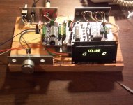
It's late but thought I'd just post a picture of what is pretty much the final pre-production board. I added a pull-down resistor and removed one of the same.
Now provides the control features I want -- control via I2C for IR and encoder and direct connection for potentiometer control. Motorized potentiometer is also possible for someone wishing to add a remote to their existing amp. The remote control board can be used stand-alone for back-fitting.
Works perfectly with older version of software, new software is much improved but has a glitch or two to clear up.
Picture is of latest test jig with all the parts needed for a full preamp. Sorry about the glare in the picture, it's late.
Attachments
I've got my main board to the point where I can consistently program it to imitate any value pot I choose (with bottom end always starting at 40 ohms) and I'm going to install PICs and LDRs in two more boards to be sure that my methods work across several samples. When they're all working as expected it'll be time for that beta testing. So far I've played with 10K and 100K pot values and they seem to perform as expected with a maximum current of 10ma to the shunt LDRs and 2ma to the series LDRs at maximum attenuation and minimum attenuation which provides a respectable 48dB of attenuation at 10K and a good 68dB at 100K.
This morning when I turned the board on in a rather cold room the pot value had shrunk from 100K to 65K at the high end. This phenomenon does not affect channel-to-channel tracking nor does it affect in any appreciable way the lower half of the range that predominately controls attenuation so I'm not too concerned.
However, I don't know enough about how the difference between 100K and 65K might affect the interaction with the input impedance of a real-world amplifier to understand the implications in that regard -- either as immaterial or important.
Could some knowledgeable person or two please comment on what kind of impact that might have on the sound? I guess it is a characteristic common to all LDR-based pots and I haven't heard of any complaints over the issue. I just thought I'd ask.
BTW, for purposes of calculating R1 and R2 at various attenuations I've settled on assuming a 200 ohm source impedance and potvalue x 2 for the theoretical amplifier load (20K amp for 10K pot). If I've got it really wrong would someone please say something. Thanks.
Ah, nice -
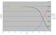
I'm not quite clear about this part for purposes of calculating R1 and R2 at various attenuations, I've settled on ... a potvalue x 2 for the theoretical amplifier load (20K amp for 10K pot)
Not sure if this says the (amp) load has a 20kR impedance for the middle curves, yes?
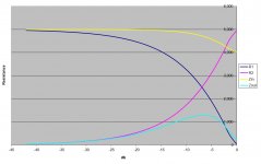
Assuming this is correct, worst case Zout of the unit is about 2.5kR at about -8dB attenuation, again generally outside most 'normal' operating conditions, and nearly meets the 10:1 ratio anyway.
Input Z (max) about 2.5kR, so well above that 10:1 ratio.
If IRC (my very faulty memory) for a higher load impedance, say 100kR, this will push up the impedance shown to the source, especially at that 0dB point, and a similar thing happens when the source Z is also lower, but would be interesting to see this plotted accurately (source Z = 10R &/or 100kR amp load) with the same 10kR attenuator settings (as per middle plot above)
I think the 10kR version this will suit most people, me included.
IMO, 40+ attenuation should be more than enough in a home system if the other unit gains are reasonable - one of the curiosities of that Warpspeed version is that it has an amazing range of attenuation but again, rarely needed, so ...
Oh, yes. I remember that a number of those digital amps have an input Z down in the 3kR region, so this could be a problem - does make it a significant characteristic of the source to supply the necessary current but doubt it's a problem for the ldrs themselves ...
I'm not quite clear about this part for purposes of calculating R1 and R2 at various attenuations, I've settled on ... a potvalue x 2 for the theoretical amplifier load (20K amp for 10K pot)
Not sure if this says the (amp) load has a 20kR impedance for the middle curves, yes?
Assuming this is correct, worst case Zout of the unit is about 2.5kR at about -8dB attenuation, again generally outside most 'normal' operating conditions, and nearly meets the 10:1 ratio anyway.
Input Z (max) about 2.5kR, so well above that 10:1 ratio.
If IRC (my very faulty memory) for a higher load impedance, say 100kR, this will push up the impedance shown to the source, especially at that 0dB point, and a similar thing happens when the source Z is also lower, but would be interesting to see this plotted accurately (source Z = 10R &/or 100kR amp load) with the same 10kR attenuator settings (as per middle plot above)
I think the 10kR version this will suit most people, me included.
IMO, 40+ attenuation should be more than enough in a home system if the other unit gains are reasonable - one of the curiosities of that Warpspeed version is that it has an amazing range of attenuation but again, rarely needed, so ...
Oh, yes. I remember that a number of those digital amps have an input Z down in the 3kR region, so this could be a problem - does make it a significant characteristic of the source to supply the necessary current but doubt it's a problem for the ldrs themselves ...
If one chooses a 1:10 ratio for Rs to Rin then we choose a 10k pot for a 1k Source impedance.
That 10k pot has a maximum output impedance of ¼(Rs+Vol pot) = ¼(1k+10k) = 2k75
The next stage needs 27k5 to match our target 1:10 impedance ratio.
If we take it as exactly 30k for Rin then when the vol pot is at - infinity the Source sees 10k
When the vol pot is set to -0dB, the source sees 10k||30k = 7k5
The impedance seen by the source changes with the setting of the vol pot.
This is normal.
If the "Wapo attenuator" does something similar then it would APPEAR as "normal"
But the reduction of 100k to <20k is not normal. That is too much of an impedance change.
In my opinion R1 (for the 100k) needs to be much higher.
Last edited:
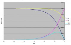
James, those three graphs are all three based on 200R source and 100K amplifier input impedance per your earlier specification. These charts are customized that way, they do NOT represent my arbitrary decision to plan LDR control around the AmplifierLoad = PotValue X 2. And if that arbitrary standard is off base, I can easily change it to whatever is appropriate.
Just came across this thread:
http://www.diyaudio.com/forums/analog-line-level/219342-help-choosing-potentiometer-passive-preamplifier.html
Obviously I've had it wrong so far -- have never really looked at this issue before so no surprise there -- and I think I'm now on the right track, just need to study this a little more. One thing I was not anticipating -- the potential value of potentiometers under 10K. I thought 10K would be the lowest really useful value.
Have built up my other two control boards and have calibrated one of them and the numbers look right so probably it'll play properly when I hook it up.
Last edited:
Here is a sentence that jumped out at me at the DACT website:
"Choosing different attenuator resistance values makes it clear, that the higher resistance values are more sensitive to load capacitance. That is also the reason why DACT always recommends using 10kOhm attenuators for passive preamp applications."
So, the suggestion is always use a 10K or lower value LDR pot??!!
A further interesting point -- their Attenuation Curve Calculator shows that for a 100K attenuator, at lesser attenuation levels the attenuation across frequencies starts to become nonlinear at frequencies well below 10KHz. That's not good.
Last edited:
- Status
- This old topic is closed. If you want to reopen this topic, contact a moderator using the "Report Post" button.
- Home
- Source & Line
- Analog Line Level
- A precision LED/LDR-based Attenuator