Oh, perfect. Here I sit in Wisconsin, USA, and so far potential beta testers are in Australia, Catalonia, and Pretoria. What's wrong with this picture??!! 😱 LOL!
I'm in Wisconsin.
I'm in Wisconsin.
Excellent! I don't feel quite so out of it anymore!
Ah, Thermal pads - that's what they're called, eh. I didn't try the difference between these ones and the basic round ones so couldn't say there was a difference in the sound with them or not, but you get one, maybe a couple if you're very careful, with these to replace a component and then you're back to stripping tracks or looping component leads, etc - I like to use those elongated pads but my pcbs aren't all that compact anyway as I'm always playing with components and like to make it easier for others also.
I don't mind anyone that's not at all interested in the differences that some components make to the sound of a system but I do find it quite surprising that some people just can't hear any difference at all
In our 'snake oil' thread here, there's some extremely aggressive posters that are just so sure that this 'cable thing' is imaginary and, of course they have to incessantly inform us of our stupidity .... I call them the 'snake oil inquisitors' as they do remind me of those intolerant religious fanatics ( might get banned for this, too!)
There are a couple of people that have the necessary gear to test the accuracy of the log curve, and a whole lot of other things - if you could get John of the "Company Store' interested, pretty sure he could do it with little difficulty - Uriah probably has the necessary gear, too.
About this minimum volume levels - I'm not much of a candidate for this as I don't often turn the sound down to extremely low levels altho I often do run it very quietly in the middle of the night sometimes - if you want to operate your system at extremely low levels, your volume control will get pretty close to that, just maybe never completely OFF - it should get down to about -40dB without any trouble - you can use a mute or turn system off if you need silence - I'm not much help here, sorry.
If the lower resistance can extend the useful 'quiet range' of the unit, it probably is worth running it at the 10mA current - would be a useful condition as a marketing point and in some people's system, maybe even necessary condition
Curiously, Allan Flores version, 'The WarpSpeed', does go completely silent - OFF - no sound at all - and it's a pretty good sounding Vol Control into the bargain - so it can be done, but I've no idea how it does it.
As for the adherence to a theoretical log curve, about 30 years ago, the guys at our local HP centre showed me the curves and the dual tracking traces of quite a few of the then 'good pots' and it was a real bad news surprise - even their 'lower priced' Allen Bradley conductive composite pots just managed to stay inside the tolerance range - so the only pots within reasonable cost are the stepper pots, and maybe some of those TVRs - as for the sound, maybe a combination of the TC2575 (naked Vishays) and those Sfernice resistors, or maybe Neohms, etc, would give a similar sound signature - not at all sure and not too interested as not a recipient of a Pools/Tattslotto win!
As '2wice' mentioned - you do have to test these things upside down in case you get an antilog curve!
Hi, folks, I'm back. 🙂
I had a thought while away from my computer -- do I really need a separate calibration board? Answer: No.
So, when i got home I did a little modification to the circuit card and, voila, no more need for a calibration board. The main board grew by two-tenths of an inch in length to 2.5" x 3.5" but that's an OK tradeoff to completely avoid the requirement for a separate board to calibrate.
Since switching between play and calibrate modes is now via an on-board jumper the input/output wires will not need to be removed from the terminal block during calibration.
Another advantage is that if someone really, really, really *has* to have automatic calibration then the headers can be mated to a daughter card to provide that capability. This is in spite of my belief that this board -- due to the low maximum current and very low current in mute mode -- will hardly ever need calibration. Neat, huh? 🙂
Onward and upward.
Good one!
As the saying goes, "Simpler, but not too simple" or "Do less, so you can do it better" (Sport Coaching)
As the saying goes, "Simpler, but not too simple" or "Do less, so you can do it better" (Sport Coaching)
I know that this doesn't make much difference with your testing & control system but with many of my 'led groups' (the 4 leds) I wrapped a couple of layers of Aluminium foils around them (ensured no contact with wires) and coated all this in wax to keep them at the same/similar temp - a follow on fron George's original idea - possibly a waste of time but .....
Nearly finished your design now - sound quality testing next ...?
Having just finished a set of tests, I thought of this issue of keeping LDRs at the same temperature by enclosing them in something.
On my board the LDRs not only are not enclosed in any material, there is a significant gap between each one, about 1/8" it looks like.
I've just completed a series of calibrations to test how consistent the results are between calibration runs. Because the tests were pretty sensitive and the results were measureable, I could see that the results do indeed shift a very little bit as room temperature varied between about 65 and 70 degrees Fahrenheit, but it's so slight that I would judge it to be totally inaudible and barely measureable as an attenuation curve shift.
I had always been skeptical that sealing LDRs together in a block would make much difference and I think I've sort of proven that to myself, at least. Maybe when we start talking 20 degree changes in temperature the curve will move noticeably, but even separated on a board, I would expect the LDRs to change similarly and thus not affect the system in any noticeably adverse way. Also, I think one reason for this stability in my control system is that I focus on current control rather than voltage control. In systems where voltage is controlled without regard to current, changes in materials temperature can change current while voltage remains constant. Since LEDs vary in brightness based on current, not voltage, and current can change due to temperature changes while voltage is held constant, controlling the voltage doesn't work well with LEDs if the temperature varies.
Anyway, here is a numerical way to look at it the changes caused by temperature in my test setup:
Total count number in one calibration cycle is about 27,000 counts. (We're talking digital control here, so the basic measure of everything is measured in counts.)
In a series of calibration runs performed back-to-back, the total deviation count of each run when compared to the average of all runs is between thirty and sixty counts. When you consider the numbers you can see that these runs are extremely consistent and most values are exactly the same and others are mostly one-count differences. Only maybe one or two values vary by more than one count and these are the high count measurements where each measurement results in a count value of maybe 400~500 so a variation of two counts is still insignificant.
When comparing calibration runs that are performed hours apart at different room temperatures as described above, the error count between runs is higher, running around 100~110 total count deviation from average. This is caused by the greater variation of result when averaging runs taken at 65 degrees with runs taken at 70 degrees.
So, the runs separated by time and temperature have count variations that are considerably higher, but nevertheless still so low that the difference should be inaudible. After all, it's still 110 counts out of a possible 27,000 counts, and the error values above one are all located at locations where the reading is in the hundreds of counts (high current and low resistance, so small errors produce little measurable difference in resistance).
Edit: Just did a series of four runs in rapid succession -- each run takes 10 minutes -- and the first test varied by 60 counts from the average, the last three varied by only thirty counts each. I guess when you do them quickly the conditions remain the same and the results are extra tight.
Last edited:
You are right to look at LED current rather than voltage.
Self heating in the LED does change the current vs voltage.
Holding constant current gives far tighter control of light output than holding constant voltage.
I too am not keen on insulating the LED/LDR from the environment.
A common heatsink tying the four devices together would be better for maintaining matching of parameters.
Over the past few days I've been working on making my external excel calculation tables more user friendly and accurate and matching them better to the way I use LDRs on the board. That part is done, and things are much better.
I have settled on a minimum resistance value for shunt of 40 ohms and a minimum resistance of 90 ohms for series. I will design the circuit to drive to a maximum of 10 milliamps but will select shunt LDRs so that they do not need that much current to achieve 40 ohms. Ergo, non of the LDRs will ever see 10 milliamps of drive in real life.
If my math is right (and no guarantee there!) 40 ohms shunt and 9960 ohms series should give me 48dB of attenuation. I hope that's good enough. Making it a 50K pot with the same 40 ohm minimum shunt it looks like a 61.5dB attenuation. If I've got this wrong will someone please point it out.
So far I've only checked ohmic accuracy indirectly using the chip, but it appears that at 40 ohms I have 1 ohm accuracy and at 10K ohms I have +/- 100 ohm accuracy most of the time. I do note that accuracy at 10K is best when the LDRs have been on for a while even at very low current. I think I would recommend that this circuit never be turned off, only "muted" which will be achieved with 2 milliamps to shunt and zero milliamps to series (about 85 ohms for shunt and 1 megaohm plus for series).
The second thing that's occupied me is value overflow at the extreme values of the pot when the 16 bit "word" I'm using is exceeded at either end and the chip wraps the value around to the other end of the value range. That's now fixed and I cannot find any problems with operation in either stereo or dual mono modes.
Next step is to replace my manual test pots with the two motorized pots I got from Mouser (which arrived without the mounting hardware that should have been there!). I had a choice -- almost $10 per nut purchased through Amazon third-party, or $5 for fifty pieces from Hong Kong. Guess which one I chose?
The temporary (without hardware) mounting of the pots won't look pretty but I hope by this afternoon I will be listening to my board for the very first time and and controlling it from across the room.
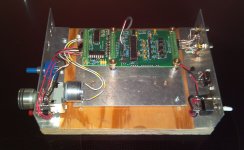
This is working (?) prototype #1. There wasn't enough space to motorize the balance control without a lot of hassle because the motor interfered with the IR card so only gain is remote controllable here.
This is not the final board design which will have the calibration circuit on the main board so no separate calibration board will be required. Also, the IR board will be connected to the main board with identical screw terminals so the IR board and the LDR board will be at the same height, and there are holes for standoffs at the front of the latest IR board for better stability.
I ran computer-controlled tests earlier and the numbers were excellent, now it's time to see if the numbers translate into good sound and hope to do that tonight.
Attachments
Last edited:
Looking forward to your results; have you another LDR attenuator on-hand to compare your's with?
Looking forward to your results; have you another LDR attenuator on-hand to compare your's with?
No, I don't have other LDR attenuators to compare to but James Hill appears to have several so I'm hoping he'll be willing to take that on. In fact, I don't have anything remotely like Golden Ears that I would trust to accurately discern subtle differences between LDR attenuators if the external factors are kept identical.
Yep, that James Hill guy, also lacking in the golden ears department, is very happy to assist in any way at all - in fact, quite impatient!
Comparisons are always 'tricky' as any new component in an established system will create differences that can be easily perceived as faults rather than mis-matches, and so on - we hear about this problem quite a bit from the better reviewers and it applies to us in just the same way & needs to be kept in mind.
I've got a couple of the LDR type units - George's original, Uriah's LighterNote, Alan's WarpSpeed and they're all slightly different and react a bit differently to different loads - not exactly sure why - ie small differences - some people do prefer a 'slightly thicker' bass line and some others prefer a cleaner sound, and so on.
I'm assisting one of the exhibitors (Continuum/Telos/Brodman/etc,etc) at our local Melb Audio Show here this w/end (a Big Deal for us!) and will see if I can organise a couple of future potential tryouts in some rather good systems, not just my humble home system &/or headphone/amps - my perceptions will be the limiting factor, I think, but quite willing ...
A curiousity at this stage, but on the rear terminal block of the main pcb, I see a couple of terminals that are labelled "+-" next to the '1IGO-IGO2' end - are these used for an external control feed for the 'mute' condition by any chance?
So, I tested the board. Actually, I just wanted to know if it worked and didn't much care how good it sounded, so quickly kluged together some stuff I had lying around -- speakers were modified dynaco A-25s (a very mediocre speaker) from 30 years ago, the amplifier was a chipamp that I had built a few years ago, and the source was CDs playing on an old DVD/VHS playback unit that hadn't been turned on in four or five years.
Results:
1. It works. Not perfectly -- I still have problems with the code because when the volume is turned almost all the way down the music suddenly gets very loud. I need to figure that one out and fix it. Also, I had to jiggle a wire to get the IR working but that was just a loose wire.
2. But the sound amazed me. I could not believe I was listening to crappy A25s. Some CDs sounded like they were recorded with too much treble boost, but some CDs sounded wonderfully more transparent than I had heard them before. I hate to say this because it'll sound phony, but the sound was noticeably clearer -- I could understand lyrics better than usual and some instruments had nuances that were new to me but sounded appropriate. I played parts of about fifteen CDs, everything from Air Supply to Yo-Yo Ma solo cello. Very nice, rather more treble than I am accustomed to hearing but there were no tone controls in the circuit and the A25s are not noted for bass. I think I was hearing the system as it truly sounds including lousy op-amps in the CD player and substandard bass from the speakers and everything. I won't say it turned my speakers into Magnepans, but while I was listening one of the thoughts I had was this system sound had moved somewhat in the direction of the full size Magnepans I listened to about a month ago.
The volume control was mostly at 12~3 o'clock and the level was quite loud; at lowest volume the level was very quiet but not silent. I did not try mute, I forgot to do that.
All in all, satisfied with the operation with caveats, and delighted to have found the pleasure of listening to a system with LDR controls.
Tomorrow back to work to figure out why the volume spikes high at minimum volume setting, that's the only remaining issue, I think. After that, connect it to some better equipment and do some extended listening.
All in all, good news, I think.
James, to answer your question re the plus and minus near the output terminal block, that was part of the circuit for the outboard calibration board. Since the calibration components are now all on the main board, the only terminal block at that end will be for the input and output wires for the audio -- one six screw terminal block.
The mute function is entirely internal to the PIC -- I simply command the shunt LDRs to be driven to about 90 ohms and I turn the series LDR power completely off and they go to above 1 megaohm. No external relay operation at all.
Ah, good that it's working okay, apart from the little glitch, and that it sounds pretty good so the rough setup has achieved the first test okay.
So far, so good - when you get it setup well, try Leonard Cohen "Gypsy's Wife" from his London Live album for a series of individual notes across the mids and the Closing Time for an integrated bass line to checkout the enhanced separation that the LightSpeed Vol control is noted for - there's many other songs, naturally but this particular mix makes it easier to discerne differences - not much top end, so another cd like the old familiar "Limehouse Blues" from the Pawnshop has a lot of 'air' and easy to hear differences and then there's Meav's 'Celtic Prayer' for a bit of a challenge....
I forgot about that neat 'mute' feature
What does this mean?..................The volume control was mostly at 12~3 o'clock and the level was quite loud; at lowest volume the level was very quiet but not silent. ...................
Most volume control pots have a working rotation of around 270° (3/4 of one Turn)
Where is the minimum on your clock?
Where is the maximum on your Clock?
What is your attenuation at 12 o'clock?
What is your attenuation at 3 o'clock?
The problem with the jumping gain turned out to be in the balance control code. All is well now, smooth as silk from min volume to max, and the balance control works exactly as it should. FWIW, when I 'slam' the pot from one extreme to the other, it takes about two seconds for the sound level to get to the new setting. So, I think the pot's rate-of-change will not be a problem at all in normal operation.
With the system I'm using it in now, at max volume it's a little too loud for comfort, and at min volume it's at the very low end of quiet listening. Muted, I can still hear the music if I put my ear up against the speaker, but in the room it's silent.
I cannot tell you what kind of gain I have in my system, but I can say that having the volume level go from very low to beyond comfortable as the pot goes from min to max is a new experience for me -- I'm accustomed to a volume control that plays well between 8 o'clock and 12 o'clock and gets scary loud beyond that; I guess my systems have always had excessive gain up until this one.
The chip in the IR remote board seems to have lost some of it's marbles, or something -- it'll decrease volume but not increase it. I need to troubleshoot that . . .
Last edited:
The chip in the IR remote board seems to have lost some of it's marbles, or something -- it'll decrease volume but not increase it. I need to troubleshoot that . . .
It turned out the marbles were all there, it was operator error. I inadvertently reprogrammed the hand-held remote and when I reprogrammed it correctly, all was well.
Have just spent several hours listening through a somewhat better system -- modified Klipsch Forte and m audio sound card instead of dynaco A25 and DVD/VHS player. Much better. I started hearing very clearly the noise floors of some of the CDs I have. At first I thought the system had some kind of LF noise problem but when I paused the source the noise went away. Became more and more aware of that phenomenon.
One last thing -- the mute control isn't as absolutely reliable as I would like it to be, sometimes it doesn't mute when I command it. I've already found the problem in the software; I need to get the board back to my main computer in order to reprogram the chip.
This has been an eye-opener for me -- I'd never heard LDRs until yesterday and only knew them by reputation. Now that I've heard them, I understand the interest.
One last thing -- the mute control isn't as absolutely reliable as I would like it to be, sometimes it doesn't mute when I command it. I've already found the problem in the software; I need to get the board back to my main computer in order to reprogram the chip.
It turns out I need to rearrange some pin assignments to make the mute operate perfectly, so that will have to wait for the next board iteration.
As a temporary fix and proof of operation I've changed the code so that turning the volume pot all the way to minimum (actually, the last 1% of travel) will mute the circuit. Works fine.
I wonder if that is a "feature" I shoujld leave in or remove when the actual mute function is fixed?
It doesn't worry me if there is an (almost) inaudible volume with the pot an minimum.
I would prefer just the mute function alone and (as an added extra) an option for the attenuator to activate a LED when the mute is on.
I would prefer just the mute function alone and (as an added extra) an option for the attenuator to activate a LED when the mute is on.
It turns out I need to rearrange some pin assignments to make the mute operate perfectly, so that will have to wait for the next board iteration.
As a temporary fix and proof of operation I've changed the code so that turning the volume pot all the way to minimum (actually, the last 1% of travel) will mute the circuit. Works fine.
I wonder if that is a "feature" I shoujld leave in or remove when the actual mute function is fixed?
- Status
- Not open for further replies.
- Home
- Source & Line
- Analog Line Level
- A precision LED/LDR-based Attenuator