The LDRs I used came close to or below 45R at 6mA. I measured very small differences in resistance for high differences in currents above 6mA. The extension of the range has a very low efficacity, with a higher risk for fast aging. They are extremely non-linear in this area. That's the reason I stopped at 6mA as that seemed the most efficient point.
But now I discovered even 6mA is too high at long term. Splitting the range in "normal use mode" and "background listening mode" with a relais seems more wise. That will be my next modif. I still have some LDRs to change the used ones to start from scratch.
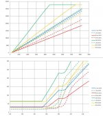
I've added graphs to make this clear. Vertical scale is resistance measured with full-scale 50kR instead of what's shown. Horizontal is current with +/- 6mA at 0 and close to 0 at max. Take care, the 6mA stays stable upto +/- 170 due to the hardware limit I built in.
Sorry to add that much in your post, I should have started this in mine...
But now I discovered even 6mA is too high at long term. Splitting the range in "normal use mode" and "background listening mode" with a relais seems more wise. That will be my next modif. I still have some LDRs to change the used ones to start from scratch.
I've added graphs to make this clear. Vertical scale is resistance measured with full-scale 50kR instead of what's shown. Horizontal is current with +/- 6mA at 0 and close to 0 at max. Take care, the 6mA stays stable upto +/- 170 due to the hardware limit I built in.
Sorry to add that much in your post, I should have started this in mine...
Attachments
Well, if its OK with wapo it sure is OK with me. I get the feeling none of you are planning to commercialize your designs just yet, and i feel that the more info and discussion around a given implementation type, the better.
I've been thinking more and more about how to achieve simple control with reasonable accuracy from the MCU, and i thought i might give PWM a try, using the built-in PWM ability of my Cortex-M4 MCU, feeding an analog integrator which in turn controls a CCS to feed the LED drivers. But if it's something that stands out in your thread especially oenboek, it's the need for increased resolution at higher attenuations settings(i.e low volume).
Also i think the dual mode with a switchable "pad" a la microphone pre's, is an elegant solution.
I'm looking hard at a cost-effective FET SSR, built from discrete components for low Rdson, to handle input selection(freeing up a bunch of LDRs to use to prolong life through paralellization), but it seems no matter what they still age, so calibration is a necessity.
Wapo and oenboek, would you consider sharing details of your designs in private with me?
Regards,
Kris
Well, if its OK with wapo it sure is OK with me. I get the feeling none of you are planning to commercialize your designs just yet, and i feel that the more info and discussion around a given implementation type, the better.
I've been thinking more and more about how to achieve simple control with reasonable accuracy from the MCU, and i thought i might give PWM a try, using the built-in PWM ability of my Cortex-M4 MCU, feeding an analog integrator which in turn controls a CCS to feed the LED drivers. But if it's something that stands out in your thread especially oenboek, it's the need for increased resolution at higher attenuations settings(i.e low volume).
Also i think the dual mode with a switchable "pad" a la microphone pre's, is an elegant solution.
I'm looking hard at a cost-effective FET SSR, built from discrete components for low Rdson, to handle input selection(freeing up a bunch of LDRs to use to prolong life through paralellization), but it seems no matter what they still age, so calibration is a necessity.
Wapo and oenboek, would you consider sharing details of your designs in private with me?
Regards,
Kris
Why in private?
Well, if its OK with wapo it sure is OK with me. I get the feeling none of you are planning to commercialize your designs just yet, and i feel that the more info and discussion around a given implementation type, the better.
Wapo and oenboek, would you consider sharing details of your designs in private with me?
Regards,
Kris
Kris,
Unlike another thread dealing with LDRs, I welcome any discussion on the subject with any slant, I'm not feeling protective.
I am long retired and I started out my search for an LDR control as pure hobby and (I thought) collegially with other folks who were interested in LDRs. Over time, however, it became apparent that I was swimming in a school of fish with strong territorial defenses and sharp teeth. The last time I tried to be collegial I got *really* bitten and decided I needed to be on my own, and maybe also justify other's worst fears and turn my discoveries into a commercial product.
")
That's where I am now, with an attitude far from what it was when I joined diyaudio some years ago. When I do publish my circuit one way or another I think you will find that it is very simple hardware-wise but supported by some pretty sophisticated software. Without the software, a knowledge of the hardware would not be of much benefit. I guess this is also why it hasn't worked out as a joint effort -- not many folks can work with the software and it's a crucial piece of my solution.
BTW, any control solution involves a very large control range -- say, 10 milliamps down to about 2 microamps -- and that's the challenge. If you treat that range with a linear control, it's a huge dynamic range and there's the rub -- computer control is linear, the LDR is logarithmic. How to get enough resolution at the low current end to make this work is the main issue.
A typical PIC is 10-bit which gives 1024 levels. The Tortuga Audio folks seem to be using a 12-bit DAC to achieve 4096 linear slices which gives better resolution at the high end. Keep in mind that the last 10% of the linear control covers the entire resistance range from about 400 ohms to the upper limit of, say, 10K ohms. So the resistance range from 400 to 10K is controlled by only 100 slices unless you increase the resolution beyond the standard 10 bit 1023 slices. If you can do this, then you've got the tiger by the tail . . .
A typical PIC is 10-bit which gives 1024 levels. The Tortuga Audio folks seem to be using a 12-bit DAC to achieve 4096 linear slices which gives better resolution at the high end. Keep in mind that the last 10% of the linear control covers the entire resistance range from about 400 ohms to the upper limit of, say, 10K ohms. So the resistance range from 400 to 10K is controlled by only 100 slices unless you increase the resolution beyond the standard 10 bit 1023 slices. If you can do this, then you've got the tiger by the tail . . .
When I do publish my circuit one way or another I think you will find that it is very simple hardware-wise but supported by some pretty sophisticated software.
Have you received your new PCB? ...just waiting on the hardware side!
You can find my design in my original thread. If you miss something let me know.Wapo and oenboek, would you consider sharing details of your designs in private with me?
I will start correcting the stuff. I will put it online as soon as it's done.
The fun is in sharing things, not in hiding them...
I tried several things, one was en exponential amp. But the only thing that really worked for me was putting a 2nd LDR in the feedback loop of the opamp. That makes the thing 100% lineair, except at the very low resistance range. The reason is (I guess) that in that area the differences between the 2 LDRs starts to play.BTW, any control solution involves a very large control range -- say, 10 milliamps down to about 2 microamps -- and that's the challenge. If you treat that range with a linear control, it's a huge dynamic range and there's the rub -- computer control is linear, the LDR is logarithmic. How to get enough resolution at the low current end to make this work is the main issue.
I also use a 13bit-DAC to have a big resolution (8000 steps). It's maybe not that important but cost is not higher.
With 13bits noise needs to be extremely low. That's why the audio-part with DAC is 50cm far from the CPU, linked by I2C. There is only digital communication when there is a change in volume or input. I also reduce noise on the LEDs by slowing down the opamp-circuit.
There are 100 other ways, and this one isn't the easiest and for sure not the best. But it works, and I had fun calculating and setting up the circuit.
Have you received your new PCB? ...just waiting on the hardware side!
If you're talking to me, yes, I've had it for a while and my thinking has already obsoleted it!
When I ordered the board I had two separate paths -- one more complex and very accurate and the other simple but less accurate. I think I've found a way to combine the methods into simple & accurate. Am now on vacation, need to get home and breadboard my idea and also do some spreadsheeting to verify the math. If it works, it'll combine the best elements.
@oenboek, For 12 bit DACs and up my understanding is that power must be very clean and very stable. Do you use a super clean supply or do you think an LM317 is good enough?
Having fun and arriving at a solution you are happy with is key in any DIY endeavour, and probably why DIY is so satisfying. While the DAC solution has appeal indeed, i want to give it a try doing it a bit differently, and use the PWM outputs of my MCU. They are high-res(16 bit) and there are twelve of them. I think i want a way to both check the actual currents produced by my pwm-controlled current source, as well as the resistances given by the LDRs at various set points. I'm still figuring out how to do calibration without needless complexity added, assuming i won't have to disconnect or mute my sources or power amp while doing it.
And i feel a strong urge to try a mosfet relay for input switching as well as "night-mode" attenuation pad, if only those sub-mOhm parts werent so damn pricy! But i think 2-3mOhm will be fine as well. Getting this far will enable me to utilize more LDRs, either parallelling them, or as ununsed "hot" spares(Air Force-style), ready to be pushed into service when the current ones drift too far away. If only there were a curve of derating over time vs current of the LDRs.
First step is to get the PWM-current source working with just the unmodified LDR board i have now, as both of you said, the magic is in the software.
Last edited:
I use very clean shunt power supplies. The website I bought the PCBs from is dead. They were called "Gold ref PS". I use a goldref +5V and a +/-12V.@oenboek, For 12 bit DACs and up my understanding is that power must be very clean and very stable. Do you use a super clean supply or do you think an LM317 is good enough?
A similar thing is the power supply used by Salas in the DCB1, but the one from Salas is even cleaner I guess.
With more noise on the PS, you loose some resolution, but the slow reaction of the LDR will average the noise out which brings resolution back (OK, this is a bit of a rough statement, but averaging helps). I don't think it's that important to have 12 or 13 bits, but it doesn't hurt. I used 4 pieces MCP4728 costing less then 2€/pc.
BTW: Same is true for the ADC if you do calibration. And for sure same for current source, voltage ref etc. For calibration I do averaging of the ADC-results as well. That's similar to adding bits.
In defining precision, you have to consider not only the number of counts that spans a resistance range -- a linear 1023 count ADC has very limited counts to cover the 9K-10K range of a 10K Log LDR pot -- but also the width of each count which determines the accuracy in maintaining a resistance value once attained.
The number of counts defines the ability to target a specific resistance. The *width* of the count defines how closely the LDR can be held to the target resistance. The second requirement is not so obvious as the first. For example, if five counts cover 1K ohms of resistance, each count is 200 ohms wide, and the LDR would have to vary by at least +/- 100 ohms before the processor would detect the change and correct for it.
Also, the correction would be considered complete if the resistance falls anywhere in the 200 ohm range of the target count. Fortunately, this problem is masked by the fact that the attenuation of a pot is always primarily controlled by the smaller of the two resistances and there always are more counts available to define a resistance at the lower end than at the upper end of a logarithmic LDR.
A 12-bit or 13-bit DAC isn't much better than 10-bit at the low end of the resistance range, but makes the device much more accurate at the upper end.
While the DAC solution has appeal indeed, i want to give it a try doing it a bit differently, and use the PWM outputs of my MCU. They are high-res(16 bit) and there are twelve of them.
First step is to get the PWM-current source working with just the unmodified LDR board i have now, as both of you said, the magic is in the software.
Back from vacation. While gone, I redid the physical layout and schematic to reflect my latest idea -- the "simple and accurate" solution. Now need to breadboard the rearrangement and verify the theoretical result. The board has shrunk to 2.4 x 3.4 inches.
@Kris, I am not aware of a PIC that delivers 16-bit resolution for anything, let alone PWM. My understanding is that PICs top out at 10 bit sensing because circuit noise and power regulation make more bits pretty useless.
Are you talking about a chip like the TLC59711? I was not aware of them until your comment made me look into it. One question I have is the accuracy specification -- +/- 1% -- which sounds good but if it's 1% of full scale, then I wonder if it's accurate enough at the low current end of LDR operation. I find I need control between 12ma and 3ua and I have resolution to +/- .2ua at the low end. If you want to verify operating current with feedback, then your feedback sensing must have the same or better bit rate as the PWM.
Pretty interesting idea. I must say, wish you well with it -- I think you're in new territory!
Are you talking about a chip like the TLC59711? I was not aware of them until your comment made me look into it. One question I have is the accuracy specification -- +/- 1% -- which sounds good but if it's 1% of full scale, then I wonder if it's accurate enough at the low current end of LDR operation. I find I need control between 12ma and 3ua and I have resolution to +/- .2ua at the low end. If you want to verify operating current with feedback, then your feedback sensing must have the same or better bit rate as the PWM.
Pretty interesting, Adafruit has a nice ready available board to use:
https://learn.adafruit.com/tlc5947-tlc59711-pwm-led-driver-breakout/overview
There is a point beyond which there is no value in added resolution in one link of the chain when it comes to controlling an LDR with a 'reasonable' power supply. I'm guessing that point is around 12-to-13 bits of resolution. The DAC/PWM may have 16 bit resolution but that level of precision will be overwhelmed by factors introduced by the other links in the chain.
Have done a new prototype board with the 'cheap AND accurate' layout and it works really well. Am now doing some nips and tucks around the edges and working on the very last piece of the software suite.
At the level of resolution I'm working at, a clean power supply is essential and I've stepped beyond the standard LM317 supply. An article I found very interesting and is influencing my design is this one:
//http://www.maximintegrated.com/en/app-notes/index.mvp/id/883
I'm not interested in going way way out there like some of the shunt designs have done, but I'm perfectly happy to add a preregulator and an extra ceramic for reduced noise on the line.
//http://www.maximintegrated.com/en/app-notes/index.mvp/id/883
Sorry, that should be Improved Power-Supply Rejection for Linear Regulators - Tutorial - Maxim
Aah!
I went for a trawl thru their listing and ended up in that same Tutorial 883 and they suggest that with a simple R-C filter in front of one of their MAX8867 reg chips, you can get something better than a -70dB noise supply, or 2 reg chops in series for a similar/better result -
In their test data results, I would assume a very clean 'raw supply' to the Device Under Test (as they say!) -
To get something similar will require a fairly well built input 'raw supply' (ie reduce noise from the line, transformer secondary/diode supply, etc ) and maybe a simple Salas shunt reg might be worth trying, or perhaps a simpler C-multiplier after the primary 'raw dc' filter cap.
I vaguely remember a thread that suggested that in some circumstances, a well designed series reg will produce a better result than a shunt reg - I think it was in relation to DAC chip supplies that is more in line with your system - not any recommendation, but just something to keep in mind
As you mentioned, just how critical this supply quality needs to be will depend on the level of diminishing returns, or any benefit at all.
It's progressing fairly steadily now - looking forward to how it works/sound in practice (ahem, a music rest ...?)
James, I'm acutely aware of the 'diminishing returns' you mention, but my design can deliver an equivalent resolution bit rate of 13+ bits, and that's getting into the range where noise on the power supply does have an impact.
I don't think it will affect sonics, though, because the LED/LDR relationship has a slow response time and it seems likely that any small variation in the drive current will be smoothed out by the inabiloity of the LDR to instantaneously react to the small change in brightness. Where it becomes important is in the resolution of resistance level at the high end of the resistance range.
Can't do a listening test until the software is complete. We've had a mob at the house for the past two weeks, and they leave tomorrow. Two days of 'recovery' time, then I'll spend an afternoon digging into the software and get it done.
Because the power supply is entirely separate from the signal path (no amp or anything like it), as long as the supply is well-regulated and reasonably quiet I frankly cannot see how the power supply could affect the quality of the sound -- surely that is entirely a function of the LDRs and the connections between the source and load through the LDRs?
Yes, the ability to accurately control those higher resistance values is the 'cream' IMO! Especially without having very highly matched devices.
I remember with the current drive cct of Peter Rootzant (pietgers, post #1000 in George's original thread, back in '08) it sounded quite significantly different to the basic unit of George's, and this also changed with power supplies and/or electro caps across the leds - it created quite 'some discussion' at the time!
Both Uriah's Lighternote and the Alan's Warpspeed sound different with good and poor power supplies and this also doesn't make much sense either! [The battery supplies are just clearly better, go figure ....]
Nothing to 'agonise over' as it's simple enough to try different types when ready - just a talking point.
Yes, the ability to accurately control those higher resistance values is the 'cream' IMO! Especially without having very highly matched devices.
I remember with the current drive cct of Peter Rootzant (pietgers, post #1000 in George's original thread, back in '08) it sounded quite significantly different to the basic unit of George's, and this also changed with power supplies and/or electro caps across the leds - it created quite 'some discussion' at the time!
Both Uriah's Lighternote and the Alan's Warpspeed sound different with good and poor power supplies and this also doesn't make much sense either! [The battery supplies are just clearly better, go figure ....]
Nothing to 'agonise over' as it's simple enough to try different types when ready - just a talking point.
For best possible effect I have decided to run dual power supplies -- one to handle the digital PIC and associated circuitry, and a separate one to provide current for the LDRs; both are LM317 circuits. The hardware is now locked in, and in final stages of software.
Have just run the calibration routines with different target values and "built" both a 50K and a 100K pot from the same LDRs that I've been using to build 10K pots. The 100K is pushing the limit for a pot starting at the low end of resistances due to the span of values and control becomes sloppy well before 100K at around 80K, but at 100K the result is a 70dB pot. Ha!
Selected LDRs could no doubt be used to create an even higher resistance pot, but you'd have to sacrifice the low values somewhat.
Last edited:
- Status
- This old topic is closed. If you want to reopen this topic, contact a moderator using the "Report Post" button.
- Home
- Source & Line
- Analog Line Level
- A precision LED/LDR-based Attenuator