[snip]But at microwave frequencies capacitor B is not formed because the shield reflects the RF even if it is not grounded, like a dish reflects microwaves.[snip]..
I don't think that is how it works. RF or EMI causes a field that sets up current into the cable (screen) which couples into the signal conductors.
That is usually much lower in freq than microwave signals used with dishes, afaik.
jd
it's down to that loop area.
To minimise interference the loop areas must be minimised. This applies to receiving system and transmitting systems.
The AC cable coming into your amplifier should have the flow and return closely coupled together to minimise the radiated field that will affect surrounding equipment.
To minimise interference the loop areas must be minimised. This applies to receiving system and transmitting systems.
The AC cable coming into your amplifier should have the flow and return closely coupled together to minimise the radiated field that will affect surrounding equipment.
so you cannot accept the simple answer. Then go and look at how everyone does it? And then try to explain to yourself why they do it that way.This is not a technical answer, we are trying to improve things or at least to explore the possibilities.
so you cannot accept the simple answer. Then go and look at how everyone does it? And then try to explain to yourself why they do it that way.
Or ask at the diyaudio...
")
Last edited:
So, in either frequencies RF is coupled...
Thus there is no good of using coaxials this way...?
I think what you want to do is to insure that the coupling in both the hot and gnd is identical so there is no net interference signal. It's not realistic to expect 100% screening.
jd
Since we are talking about coaxials a bit..
the cost of a silver plated twisted cable is very high. RG223 coaxial can be found in low cost and it's internal conductor and shields are silver plater copper. It has a 100pf/m shunt capacitance.
Does it make sense to use coaxial for the speaker cables, the standard way, central conductor positive, shield grounded.
Alternativelly I could rip the shield off and twist the central conductors (and also their insulation) together, to form a twisted cable.
Which one should I prefer for better characteristics?
Last edited:
Since we are talking about coaxials a bit..
the cost of a silver plated twisted cable is very high. RG223 coaxial can be found in low cost and it's internal conductor and shields are silver plater copper. It has a 100pf/m shunt capacitance.
Does it make sense to use coaxial for the speaker cables, the standard way, central conductor positive, shield grounded.
Alternativelly I could rip the shield off and twist the central conductors (and also their insulation) together, to form a twisted cable.
Which one should I prefer for better characteristics?
Unless you are living nextdoor to a radio transmitter, and unless your power amp has the output termination wrong, you won't here a difference either way. So I would go for lowest cost
jd
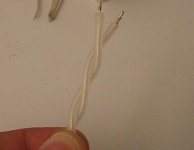
After your useful advices I have decided to make the speaked cables like this shown in the photo.
They are composed of a pair of RG223 central conductors with thei insulations, twisted together. This ensures minimum dielectric contact and at the same time noise won't affect the cable..?
Is the way I have done it right?
Also, can I use the same configuration for interconnections? Will this impose a gain in relation to the coaxial?
Attachments
Some technical links regarding shielding
Page 19 of the following link:
http://www.nutwooduk.co.uk/pdf/Issue82.PDF
and this may be of interest:
http://www.compliance-club.com/pdf/DesignTechniquesPart2.pdf
Page 19 of the following link:
http://www.nutwooduk.co.uk/pdf/Issue82.PDF
and this may be of interest:
http://www.compliance-club.com/pdf/DesignTechniquesPart2.pdf
The two coax system as described has no benefit.
1. The inductance of the loop will be directly related to the center to center wire spacing. The shield metal will not affect this.
2. The capacitance will work as a divider. In essence, there will be three capacitors here, one representing each coaxial center to shield, and the shield to shield capacitance. Given spacing, the dielectric ratios, and the ratio of dielectric effective area, the coax capacitance can be ignored, and the capacitance will be dominated by the shield to shield spacing.
3. For ALL transmission line pairs regardless of construction or connection details, the equation is:
LC = 1034 EDC...L in nH per foot, C in pf per foot. EDC is the effective dielectric constant...it will never be less than 1..ever. 1 represents lightspeed. (edit: the velocity of propagation w/r to light..is Vprop=1/sqr(EDC). If the EDC is 4, vprop is 1/2 lightspeed.) EDC less than 1 is superluminal, that ain't happenin...
For a constrained system, such as a coax, a high aspect ration stripline, or ten or 20 pairs of paralleled cat5e, this is the exact equation, and EDC drops to the relative dielectric constant of the insulation.
For systems which are not fully constrained, this equation represents the LOWER limit for the LC product. Not fully constrained is any t-line which allows either E-field or M-field to exist outside the geometric system.
4. As a result of the loop area, this configuration as an input cable will be susceptible to time varying flux loop intercept interference. IOW, it will susceptible to hum and noise interference caused by the real world.
5 As a result of the floating shield which is capacitively coupled to the hot signal, this system will be susceptible to time varying e-fields.
This setup provides no benefit with respect to noise rejection as a result of the floating shields, and spacing will allow magnetic coupling.
If the loop impedance for the circuit is greater than 377 ohms, the e-field will be the major contributor. If it is below 377, it will be the m-field.
Cheers, John
Last edited:
Since the distance from my amplifier to the speaker is 2m I think a 100pF/m shunt capacitance coaxial will not do much harm at such low impedances.
besides RG223 has very good quality conductors and double shield, no way for interference to pass in.
My feeling is that if lengths are kept low shunt capacitance should not be actually a problem even when using coaxials.
I mean, it is better to ensure a good shielding...?
besides RG223 has very good quality conductors and double shield, no way for interference to pass in.
My feeling is that if lengths are kept low shunt capacitance should not be actually a problem even when using coaxials.
I mean, it is better to ensure a good shielding...?
Or just get a lower capacitance cable such as RG-114/A 6.5pf/ft .405” OD
It's a little thick though.
see chart
Coaxial Cable Data - The D.U.C.K. Project
It's a little thick though.
see chart
Coaxial Cable Data - The D.U.C.K. Project
thick is not a problem,
the problem is where I can find it... none on ebay.
Any sources?
Alternatively, I think RG179 could be a good option for interconnects. Silver plated, thin, flexible and 64pF/m compared to the 20pF/m of the hard to find RG114.
for say 33cm lengths this will give 21pF compared to the 6pF of the RG114... not too bad
Last edited:
Hi J,
thanks for that.
I don't understand half of it, but I accept what you are telling us.
Sorry about the gibberish..
Basically, there is no difference between the described setup, and using two unshielded magnet wires spaced the same distance apart as the cables. The inductance will be the same, and the capacitance will be within a few pf. But since the wires are not together, they will be sensitive to external noise.
I think the basis of what Jneutron is saying is the unconnected shields will act as very good antenna's and quite wideband, picking up any stray noise, a few radio stations (FM), cell phone squarks etc.
Yup. As well as a whole lotta hum and pops and tics.
Cheers, John
- Status
- This old topic is closed. If you want to reopen this topic, contact a moderator using the "Report Post" button.
- Home
- Source & Line
- Analog Line Level
- An ultra Low Shunt Capacitance way for audio interconnections (LSC configuration)