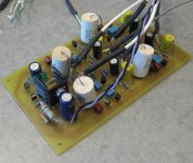
Attached is a stab at an active crossover based on unity-gain Sallen Key filters built around a simple current source loaded JFET source follower. The circuit is designed to run on a single supply to accomodate my preamp setup, which uses simple single ended jfet/mosfet-based circuits running off an external 40V unregulated supply. Each functional block inside the preamp (RIAA amp, line amp) has its own on-board regulator. This will be the third functional block so I can finally biamp my system. I deliberately used a simple follower this time around - one obvious frill would be to add a load resistor and cap to each follower as well as changing resistors R16, R22, R27, R34, R45, R48, R54, and R62 to change the simple followers to "FETWhites" for lower output impedance. Folks using +/- supplies might want to consider complimetary followers and/or servo circuits, as the latter would allow eliminating some output coupling caps.
This one is already built up, and will go into my preamp test setup when time allows.
This one is already built up, and will go into my preamp test setup when time allows.
Attachments
At present RIAA amp is a circuit from my "JFET SRPP" thread. The line amp is a "gm boosted" mosfet/darlington follower (I don't think I've published an explicit thread on that circuit). The power amp is currently my "Shrine" cascoded JFET/ultralinear 1625 SE tube amp.And a JFET/Mosfet class AB amplifier.It's sitting on top of my "Gain Clown" composite chip amp. The speakers are a pair of hexagonal prisms I built out of particle board in 1979, loaded with 16 each of a Vifa/JBL 4" driver from pars express and 3 X vifa soft dome tweeters. The setup is pretty much omnidirectional, with 4" drivers on 5 of the six faces of the prisms, and the tweeters on the three most forward-facing sections.
Hi,
basically you can use any Buffer You like. The main characteristics of a buffer stage is a gain of unity or close to one, high input- and low output impedance.
When You look at different filter topologies, You will mostly find the triangular OP-Amp symbol as the active or gain-device. If the gain is one (direkt wire connection from the output of the device to its negative input) You can basically choose any buffer You like, wether it be JFET-buffers with single or dual supply, or triode tube buffers, or bipolar transistor buffers or MOSFET buffers. Wether it be very simple source-, cathode or emitter-followers with resistor load or current source load (as in this case).
In line level circuits I´d use JFETs in first place and triodes in second. They are the best devices for this application. The only advantage of MOSFETs is that there are a lot of complementary devices around, while there are no P-types with tubes and only a few P-JFETs. In a simple Buffer circuit this is of no disadvantage, because there is nothing like a true complementary transistor anyway and the N-channel only circuits work extremely well.
On Erno Borbely´s website You find nice descriptions of basic JFET-circuits that suite this application nicely.
If You´re intersted in music I can only recommend to try those current source loaded Source follower circuits. You probabely will never use OP OP amps in such applications again.")
jauu
Calvin
basically you can use any Buffer You like. The main characteristics of a buffer stage is a gain of unity or close to one, high input- and low output impedance.
When You look at different filter topologies, You will mostly find the triangular OP-Amp symbol as the active or gain-device. If the gain is one (direkt wire connection from the output of the device to its negative input) You can basically choose any buffer You like, wether it be JFET-buffers with single or dual supply, or triode tube buffers, or bipolar transistor buffers or MOSFET buffers. Wether it be very simple source-, cathode or emitter-followers with resistor load or current source load (as in this case).
In line level circuits I´d use JFETs in first place and triodes in second. They are the best devices for this application. The only advantage of MOSFETs is that there are a lot of complementary devices around, while there are no P-types with tubes and only a few P-JFETs. In a simple Buffer circuit this is of no disadvantage, because there is nothing like a true complementary transistor anyway and the N-channel only circuits work extremely well.
On Erno Borbely´s website You find nice descriptions of basic JFET-circuits that suite this application nicely.
If You´re intersted in music I can only recommend to try those current source loaded Source follower circuits. You probabely will never use OP OP amps in such applications again.
jauu
Calvin
Well, yes, any buffer will more or less do. I chose a minimum parts count deal with only two active devices that will work well with my single power supply system. Current source loaded buffers are supposed to be better in terms of distortion. Audio magazine had a piece on that topic as far back as the late '70s. If I have a little time tomorrow, I'll simulate a passive vs. current source loaded jfet buffer to document the difference. A bipolar transistor with a ring-of -two current source load would also work. A complementary circuit with, say, 2SK170 and 2SJ74 (see Borbely) would also work very nicely, it's just counter to the philosophy of my current preamp scheme, which was to avoid using exotic Japanese devices if possible. It is quite possible, as it turns out.
The main thing is to choose a scheme and just do it. As I said before, I think that the overt effect of biamping vs. a passive crossover will most likely swamp out differences in filter implementation, unless the filter circuit is really crap for some reason. Even opamps, done properly, will likely sound better than a passive crossover.
The circuit topology I've shown would work with triodes and jfets, with some intelligent redesign.
Hi,
You may know that I build electrostats (excellent ones I may add)
ESLs can be still the most revealing machines regarding fine detail, resolution and naturality of sound.
They reveal sonic differences between a OPamp- and a JFET-buffer-crossover of otherwise identical schematics easily.
With those systems I made the experience that OPamp crossovers always sounded like HiFi and reproduction, but the JFET-Buffers added emotionality and a life-like quality. They sounded like music and made You forget sitting in front of technical gear. I regard this quality -or better the lack of it- as one of the biggest drawbacks of the typical active speaker designs which are equipped with OPamp crossovers. I think that this is the major reason why many people still prefer passive speakers or even regard them as superior.
jauu
Calvin
You may know that I build electrostats (excellent ones I may add
)ESLs can be still the most revealing machines regarding fine detail, resolution and naturality of sound.
They reveal sonic differences between a OPamp- and a JFET-buffer-crossover of otherwise identical schematics easily.
With those systems I made the experience that OPamp crossovers always sounded like HiFi and reproduction, but the JFET-Buffers added emotionality and a life-like quality. They sounded like music and made You forget sitting in front of technical gear. I regard this quality -or better the lack of it- as one of the biggest drawbacks of the typical active speaker designs which are equipped with OPamp crossovers. I think that this is the major reason why many people still prefer passive speakers or even regard them as superior.
jauu
Calvin
Not everybody has speakers as discerning as that. I suspect the main reason for passive crossovers predominating is cost for the manufactured speakers, and inertia for those who build their own. I'll plead guilty to the latter. Passive crossovers are designed to operate into a fixed impedance, while speakers are really anything but. The difference in control with the amp connected directly to the speaker without the intervening impedance of the crossover should make quite a difference. I'll report back once I make the change.
For grins and info, here's a comparison between current source loaded and non-current source loaded source follower with similar bias. Simulation was performed in Pspice with the device models provided there. First, a source follower with just resistive loading.
Attachments
Hi Wrenchone,
For now, i am using 24db L.R. op amps crossovers which are the weak point in my system.
I am interested in transpearent crossovers such as yours.
Trying to understand your schematic...
You use two stages for each filter. Is the first one a buffer only or does it participates to the filtering?
Which slopes do you get? Which alignment?
The two fets in front of each stage are a simple buffer, so that each filter is fed by a low impedance. Since I mean to have a level pot in front of each filter, this part was pretty important. It allows one a lot more freedom in choosing a value for the level pot, so that I don't load down the line amp that's driving the crossover. The filter stages are 12 dB/octave, and the alignment is meant to be Linkwitz-Riley. Right now I have the filters set for about 5kHz.
The two fets in front of each stage are a simple buffer, so that each filter is fed by a low impedance. Since I mean to have a level pot in front of each filter, this part was pretty important.
Do you mean coupled pots to get a common level? That is how is made my dbx crossover. There are separate output pots also, to compensate the speakers efficiencies.
Do you think 12db/octave are enough for a tweeter down to 2000Hz (Fs=650Hz)?
Is it possible to cascade two identical second stages to obtain 24db?
Last edited:
I intend to use a couple of dual pots for my crossover, but there's nothing stopping one from using a separate pot for each filter, so you can both set level and adjust for sensitivity differences between a pair of speakers.
This is just my opinion, but I would want a steep crossover for a tweeter with low resonant frequency to keep it from being overdriven by low frequency. Making a 4th order filter is fairly straightforwrd - use the buffer in front, then cascade two filter stages. The two cascaded stages will need a different Q than the single stage filter for proper alignment. All this is described in concise detail in Linkwitz's web site on active crossovers. Do a search for "Linkwitz-Riley crossvover", and it's one of the first things to pop out. The Rane paper on crossovers is also useful reading.
This is just my opinion, but I would want a steep crossover for a tweeter with low resonant frequency to keep it from being overdriven by low frequency. Making a 4th order filter is fairly straightforwrd - use the buffer in front, then cascade two filter stages. The two cascaded stages will need a different Q than the single stage filter for proper alignment. All this is described in concise detail in Linkwitz's web site on active crossovers. Do a search for "Linkwitz-Riley crossvover", and it's one of the first things to pop out. The Rane paper on crossovers is also useful reading.
Here's a representative schematic for a 24dB HP filter in the style I've been using so far. The R's and C's for frequency/Q determination are left open for whatever the experimenter has available. All the Cx values will be equal. The Rx and RY values are chosen and ratioed for the required crossover frequency and Q. The Linkwitz site on active filters (Google is your friend...) is an excellent and concise guide for this.
I use the PN4393, as it is a good middle-of-the-road fet cheaply available from sources like Digi-Key and Mouser. You can be snobby and use something like the 2SK170 (or a BC-style Euro-fet for that matter), but You'll have to adjust the values on the current sink resistors for appropriate operating current. Adding some bypass caps across the power supply wouldn't hurt, either.
I use the PN4393, as it is a good middle-of-the-road fet cheaply available from sources like Digi-Key and Mouser. You can be snobby and use something like the 2SK170 (or a BC-style Euro-fet for that matter), but You'll have to adjust the values on the current sink resistors for appropriate operating current. Adding some bypass caps across the power supply wouldn't hurt, either.
Attachments
- Status
- This old topic is closed. If you want to reopen this topic, contact a moderator using the "Report Post" button.
- Home
- Source & Line
- Analog Line Level
- JFET Active Crossover