Hi,
I am new to electronics and I have chosen as my first circuit to attempt to implement the design described here:
Audio masterclass
It's based on the reference design in the INA217 datasheet:
but omits a few elements.
I have wired it up on a prototype board, and checked that the voltages on the supply rails are at -15 and +15, checked the phantom power voltage, which all seem fine, but I can't get it to output anything.
I'm not looking for anyone to pick over my picture, but if someone feels like it")
It would be a massive help if anyone could give me some clues about how to diagnose the issue armed with a multimeter, or failing that, where to go next, recommended books, or other resources.
Here is a picture of my attempted implementation:
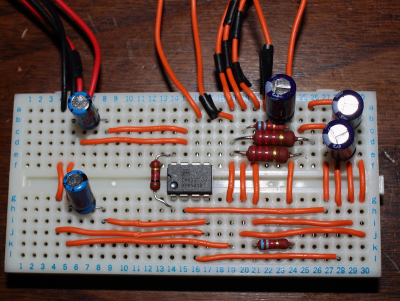
Inputs/outputs:
4: -15V
5: ground
6: +15V
16: Vo
19: XLR 1
20: XLR 2
21: XLR 3
22: Phantom power ground
24: Phantom power +45V
Thanks for reading.
I am new to electronics and I have chosen as my first circuit to attempt to implement the design described here:
Audio masterclass
It's based on the reference design in the INA217 datasheet:
An externally hosted image should be here but it was not working when we last tested it.
but omits a few elements.
I have wired it up on a prototype board, and checked that the voltages on the supply rails are at -15 and +15, checked the phantom power voltage, which all seem fine, but I can't get it to output anything.
I'm not looking for anyone to pick over my picture, but if someone feels like it
It would be a massive help if anyone could give me some clues about how to diagnose the issue armed with a multimeter, or failing that, where to go next, recommended books, or other resources.
Here is a picture of my attempted implementation:
Inputs/outputs:
4: -15V
5: ground
6: +15V
16: Vo
19: XLR 1
20: XLR 2
21: XLR 3
22: Phantom power ground
24: Phantom power +45V
Thanks for reading.
the circuit shows 2 op amps but I see only one in the photo. Also you know you are building a Microphone preamp right?
The op amp shown in the circuit is optional, and allows Vo to be trimmed if required. It's omission does not stop the basic functioning of the circuit.
The INA217 isn't an op amp, it's an instrumentation amp.
Yes I know it's a mic pre-amp. I have the XLR end plugged into an AKG C3000 and the other into my USB audio line in.
I'm fairly sure the basics are in place, maybe there is a mistake in the wiring, maybe a component is faulty, I'm just not experienced at debugging circuits and looking for pointers.
Thanks
OK, here we go...
turn off
disconnect the source from the circuit
disconnect the power supply from the circuit
double check everything is routed properly on your proto-board
double check all values (...easy to get a resistor out by x10 !)
(make sure you have not got inulation accidentally poking down into a hole)
turn on
measure the power supply
turn off
connect power supply to circuit
turn on
check power is available at pins 7 and 4
turn off
connect source
turn on
activate source
check output from circuit
.......................................................
You also need to check that the source is working. Alternatively replace the source with one that you know is working... or build one... just a small 555 based oscillator... the 'net must be teeming with them!
: )
turn off
disconnect the source from the circuit
disconnect the power supply from the circuit
double check everything is routed properly on your proto-board
double check all values (...easy to get a resistor out by x10 !)
(make sure you have not got inulation accidentally poking down into a hole)
turn on
measure the power supply
turn off
connect power supply to circuit
turn on
check power is available at pins 7 and 4
turn off
connect source
turn on
activate source
check output from circuit
.......................................................
You also need to check that the source is working. Alternatively replace the source with one that you know is working... or build one... just a small 555 based oscillator... the 'net must be teeming with them!
: )
OK, here we go...
turn off
disconnect the source from the circuit
disconnect the power supply from the circuit
double check everything is routed properly on your proto-board
double check all values (...easy to get a resistor out by x10 !)
(make sure you have not got inulation accidentally poking down into a hole)
turn on
measure the power supply
turn off
connect power supply to circuit
turn on
check power is available at pins 7 and 4
turn off
connect source
turn on
activate source
check output from circuit
.......................................................
You also need to check that the source is working. Alternatively replace the source with one that you know is working... or build one... just a small 555 based oscillator... the 'net must be teeming with them!
: )
Many thanks for the reply.
I was thinking of applying a test voltage, but I didn't think of an oscillator. I'll try it. I'm using an AKG 3000 which works great, tested before and after the circuit test.
The rest of your points, I am happy to report I have done all of that, which makes me feel better. I've double checked all the resistors, power rails, and routing with a multimeter.
Are there any checks I can do with the multimeter on the chip itself to verify it is functioning?
I think I will just break it down and start with the simplest circuit to verify each stage, this time using a test oscillator source as you suggest. It's all part of the learning process I suppose.
I am new to electronics and I have chosen as my first circuit to attempt to implement the design described here:
I appreciate your courage, but mic amp design is one of the most difficult challange in audio circuit design.
Before you do anything, please add D1-D4 input protection diodes. Also, it would be helpful if you show us the schematics what you try to assemble exactly (paper+pencil+scan/photo) will do.
Good luck
Last edited:
an instrumentation amplifier is a type of op amp. Are you using the phantom power hook up, and does your mic need it. If yes check for power at the xlr pins, if no turn off or don't hook up phantom power. Since you are using a balanced input touching one of the input pins should give you some hum on the output. Using you finger as a signal source you can now adjust the min and max gain settings. Even though your circuit is not meant to drive headphones directly there is no real reason that you can't hook up some headphones thu a 500 ohm or so resistor and listen while you touch the input. The output should be somewhere near 0 volts without the servo circuit installed.
Are you familiar with the pin layout of the IC. Looking from the top there is usually a dot or a mark of some kind beside pin 1. In your photo pin 1 is in the bottom left corner. There should be some kind of output dc blocking cap before the next stage.
Are you familiar with the pin layout of the IC. Looking from the top there is usually a dot or a mark of some kind beside pin 1. In your photo pin 1 is in the bottom left corner. There should be some kind of output dc blocking cap before the next stage.
I appreciate your courage, but mic amp design is one of the most difficult challange in audio circuit design.
Before you do anything, please add D1-D4 input protection diodes. Also, it would be helpful if you show us the schematics what you try to assemble exactly (paper+pencil+scan/photo) will do.
Good luck
I will add those diodes once I get the parts, and I will upload an updated schematic this weekend.
Thanks.
Well, best of luck with it... worth checking that you have not got the chip in the wrong way!
Thanks for that. The chip is in the right way
an instrumentation amplifier is a type of op amp. .
OK, learning all the time. I understood that instrumentation amps differed in that they combine multiple op-amps and do not require input impedance matching.
Are you using the phantom power hook up, and does your mic need it. If yes check for power at the xlr pins, if no turn off or don't hook up phantom power. Since you are using a balanced input touching one of the input pins should give you some hum on the output. Using you finger as a signal source you can now adjust the min and max gain settings. Even though your circuit is not meant to drive headphones directly there is no real reason that you can't hook up some headphones thu a 500 ohm or so resistor and listen while you touch the input. The output should be somewhere near 0 volts without the servo circuit installed.
This instantly appeals to me as a way of testing, and again, I can't believe I didn't think of this! I will try it.
Are you familiar with the pin layout of the IC. Looking from the top there is usually a dot or a mark of some kind beside pin 1. In your photo pin 1 is in the bottom left corner. There should be some kind of output dc blocking cap before the next stage.
Don't know about the blocking cap, I'll look into this, but I'm just following the audio masterclass design in the originally provided link. Updated schematic to follow.
Much appreciated!
- Status
- This old topic is closed. If you want to reopen this topic, contact a moderator using the "Report Post" button.
- Home
- Source & Line
- Analog Line Level
- Pre-amp: INA217 reference implementation