hi
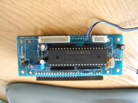
I have bought by ebay a volume remote control module with PGA 2311
the problem is that the volume starts every time with the volume level of
-46dB and does not remember the volume setting. Also the lowest volume is
-96 dB and you can still hear some sound it must be zero.
a have ask the seller to change the software of setting but the don't give
any correct awnsers. Is there a way to change the HEX file i
Crystal PGA2311 Volume remote control preamplifier kit - eBay (item 200471618932 end time Jun-10-10 20:06:21 PDT)
regards,
Harry
Hey Hendrik,
I'am testing this board now with 8515 seems to work ok
I used Danzup code as base code and edit the layout for the board
when finish testing I post the code for it
-96dB must be quiet enough to be almost silent. I can't imagine when you would need total silence - turn it off.
My PGA2311 kit from E-Bay has been problematic from the start. For a start it came with no instructions other than "Insert the components as per the silk screen". I did, only to find that the PSU diodes were the wrong way round. It still doesn't work properly. It starts up OK and drops to -96dB. Then it rises to -46dB. From there I can only reduce the volume and not increase it.
My PGA2311 kit from E-Bay has been problematic from the start. For a start it came with no instructions other than "Insert the components as per the silk screen". I did, only to find that the PSU diodes were the wrong way round. It still doesn't work properly. It starts up OK and drops to -96dB. Then it rises to -46dB. From there I can only reduce the volume and not increase it.
the ebay controller code tends to be utter crap.
if you want, you can download my arduino source code and adapt the pga engine board to use an arduino (mine is LCDuino) controller. there is a lot more features in my code and you can change the code, too, unlike the ebay/china stuff.
hth
if you want, you can download my arduino source code and adapt the pga engine board to use an arduino (mine is LCDuino) controller. there is a lot more features in my code and you can change the code, too, unlike the ebay/china stuff.
hth
Bascom AMEGA8515 CODE for China Board
' you need to modify the board a bit for this code see China_8515_sch_EDIT_THIS.PNG
Here is the code for China board using Atmega8515 fuse INT 8Mhz
download Zip file and edit PCB like in SCH
I removed the 4 sil pullups resistor network
and cut the wire at PIN 9 RESET 89C51 use reverse rest so you need to CUT here
LCD show volume as 0 - 63 but we can change it if you like db or 0-128
hi
I have bought by ebay a volume remote control module with PGA 2311
the problem is that the volume starts every time with the volume level of
-46dB and does not remember the volume setting. Also the lowest volume is
-96 dB and you can still hear some sound it must be zero.
a have ask the seller to change the software of setting but the don't give
any correct awnsers. Is there a way to change the HEX file i
Crystal PGA2311 Volume remote control preamplifier kit - eBay (item 200471618932 end time Jun-10-10 20:06:21 PDT)
regards,
Harry
' you need to modify the board a bit for this code see China_8515_sch_EDIT_THIS.PNG
Here is the code for China board using Atmega8515 fuse INT 8Mhz
download Zip file and edit PCB like in SCH
I removed the 4 sil pullups resistor network
and cut the wire at PIN 9 RESET 89C51 use reverse rest so you need to CUT here
' see http://www.diyaudio.com/forums/anal...trolers-source-selections-37.html#post2344973
' this version with 3 input, RC5 remote control & PGA2311 volume ,
' mute ,backlight LED control , with Encoder
' modified time delay for volume set
'
'Modified by FarmTech 20.09.2010 EDIT INPUT SELECT TEXT via RC5 , leran RC5
' Edit the Text for you input How do it work :
' Select Edit input text via menu button
' Upper Line Show The Current Text
' Bottom Line Is Where You Write The New Text
'
' RC5 COMMANDS FOR EDIT TEXT :
' STEP 1 : VOL - : SELECT THE TEXT TO EDIT steps from 1 to 3 in the input select text
' STEP 2 : CH + : scroll letters up
' STEP 3 : CH - : scroll letters down
' STEP 4 : VOL + : SELECT the letter , it goes next letter do step 2 to 4 until you have the text you like to use
' STEP 5 : MUTE : save the text to memery and show it on lcd use VOL- to select next or press power on/off to exit
' STEP 6 : Power on/off EXIT Edit mode
' ATT ATT :IF YOU LIKE TO EXIT AND NOT SAVE JUST PRESS POWER ON/OFF -
' 22.09.2010 LEARN a new RC5 Remote controller
' New in menu is add a new remote
' This ONLY work with a RC5 remote
' When you you enter this menu you will be ask to :
' PUSH A BUTTON = this will check if your remote is a RC5( use 1 of the buttons CH+, CH-, VOL+, VOL- or Mute )
' If NOT then it cant be used PUSH menu to exit this setup
' If it is a RC5 you can now add this to controlle your hardware
' Just 5 steps to setup buttons Power, CH+, CH-, VOL+, VOL- & Mute
' Thats it simple and easy enjoy
Encoder push button have 3 funktions :
short press select menu less than 0.5 sec
medium press Mute 1 sec
long press power ON / OFF more than 1.5 sec
LCD show volume as 0 - 63 but we can change it if you like db or 0-128
Attachments
Last edited:
I'm completely new to programming of PICs and their bretheren. How do you reprogram the PIC with the hex file ?
Hi,
First of all this is ATMEL not PIC
so if you'r setup is based on a pic I can't help you (sorry)
China ATMEGA8515 org remote
This is for update ATMEGA8515 with orginal remote (NEC)
Only for orginal remote no edit input text or change remote
I used this board
goto link and see more image of the board


This is for update ATMEGA8515 with orginal remote (NEC)
Only for orginal remote no edit input text or change remote
I used this board
goto link and see more image of the board
Attachments
Last edited:
No mine is as per your diagram. Supplied by the same Chinese supplier. I just assumed it was a PIC.
ok,
Don't know if your board have same pin layout as mine see my link to Board
You have to get a new chip ATMEGA8515 and program it with the code
and make the change on the pcb as in post
you can use many diffrent programmers for this
I use Bascom-avr and Atmel Studio
Yep, Mine looks exactly the same, just the markings on the micro are different.
Question was, How do you reprogram the new micro ?
If I need to buy a PIC (or whatever) programming board and the software to go with it, it ain't worth it. Dusty Bin can have a feast.
I only paid £19.00 for the cr*p kit in the first place.
Question was, How do you reprogram the new micro ?
If I need to buy a PIC (or whatever) programming board and the software to go with it, it ain't worth it. Dusty Bin can have a feast.
I only paid £19.00 for the cr*p kit in the first place.
Last edited:
Yep, Mine looks exactly the same, just the markings on the micro are different.
Question was, How do you reprogram the new micro ?
If I need to buy a PIC (or whatever) programming board and the software to go with it, it ain't worth it. Dusty Bin can have a feast.
I only paid £19.00 for the cr*p kit in the first place.
You need a programmer to program the chip and Fusebits
software for programmers are free on net , just be sure that the programmer can program fusebits Atmega8515 is default 1Mhz int we run 8Mhz int
I dont have time to make a long list of programmers and software so check the web for it
How can I help :
if you like I can program a chip and ship it to you
all you need is pay for chip and shipping cost from Denmark
or you can send me a chip (ATMEGA8515) and I program it) and ship back to you
before you do this check post #1 schematic to be sure it's same layout
Last edited:
I've had to send the kit back to China for the time being. The PCB that I bought had the rectifier diode silk screen orientation round trhe wrong way which caused a bit of damage. The vendor wants to see the boards.
How much would a programmed chip be ? I might just sent the kit to you so that you can verify your work before you return it, that would save any animosity due to confusion.
What crystal is on your PCB ? Mine has a 12MHz crystal.
How much would a programmed chip be ? I might just sent the kit to you so that you can verify your work before you return it, that would save any animosity due to confusion.
What crystal is on your PCB ? Mine has a 12MHz crystal.
Last edited:
I've had to send the kit back to China for the time being. The PCB that I bought had the rectifier diode silk screen orientation round trhe wrong way which caused a bit of damage. The vendor wants to see the boards.
How much would a programmed chip be ? I might just sent the kit to you so that you can verify your work before you return it, that would save any animosity due to confusion.
What crystal is on your PCB ? Mine has a 12MHz crystal.
around 10£ inc shipping cost (5.8£)
crystal is same but I see 1 Cap to lcd backlight the yellow one left site
and connectors top right is not same
but that dont mean its not same chip pin layout as mine
about the rectifier diode maybe the PGA2311 is dead from this error wrong power in +-5V
Last edited:
I think the regs protected the PGA2311. They did not output anything with reverse polarity input.
I was amazed, the two regs smoked like a burning building but were both still OK after testing. I only applied the reverse power for less that a second.
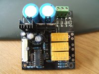
Anyway, hopefully Chinese vendor will sort that out as that was his mistake. You will notice that the four rectifiers are noe apparently the wrong way round (this is how they should be)
£10 sounds fine to me.
I was amazed, the two regs smoked like a burning building but were both still OK after testing. I only applied the reverse power for less that a second.
Anyway, hopefully Chinese vendor will sort that out as that was his mistake. You will notice that the four rectifiers are noe apparently the wrong way round (this is how they should be)
£10 sounds fine to me.
Attachments
Last edited:
Hi, KatieandDad !
Can I write your source http://www.diyaudio.com/forums/atta...l-module-pga-2311-china_8515_farmtech_nec.zip
on this chip Atmel at89c52 or I must use ATmega8515 ? Is It works?
Can I write your source http://www.diyaudio.com/forums/atta...l-module-pga-2311-china_8515_farmtech_nec.zip
on this chip Atmel at89c52 or I must use ATmega8515 ? Is It works?
")
- Status
- This old topic is closed. If you want to reopen this topic, contact a moderator using the "Report Post" button.
- Home
- Source & Line
- Analog Line Level
- volume remote control module with PGA 2311