I took this one, HD44780 compatible, 5VDC power supply, driven by a PIC.

Here is, where you can buy it:
LCD Display HD44780 2x16 BLUE 16x2 Blau white weissFSTN bei eBay.de: Bauelemente (endet 03.02.11 21:29:55 MEZ)
Price: 4.00€
Best regards - Rudi_Ratlos
Here is, where you can buy it:
LCD Display HD44780 2x16 BLUE 16x2 Blau white weissFSTN bei eBay.de: Bauelemente (endet 03.02.11 21:29:55 MEZ)
Price: 4.00€
Best regards - Rudi_Ratlos
I see there is a long ribbon cable coming off the lcd.
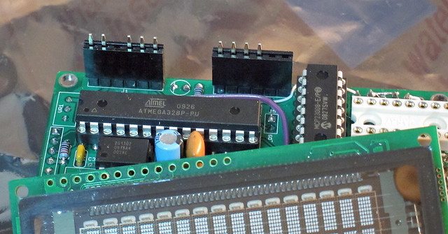
my current design and build preference is to follow a so-called 'backpack' style, such as:
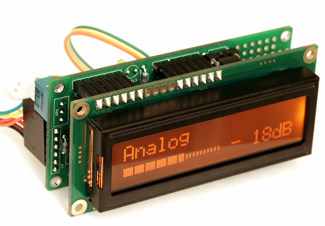
and in use on a test bed:
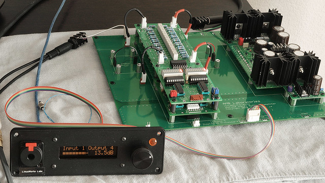
there is an LCD/IR/motorPot 'remote head' and it controls a volume control engine (that big motherboard thing) via a simple i2c+power cable. the ribbon just needs 4 wires (I use 6 to double up on power and gnd) and then it can control any downstream i2c device as well as give or get power from it (in this case, the mobo gets power and sends it *to* the display/control head).
you can see this can even be a distributed setup where the remote head is in one fancy display box and the back-end that handles the mess of wires is somewhere else. you *can* put them in the same box, but you don't *have* to. control is digital and audio path is pure analog.
anyway, I now try to do my control over i2c instead of bulky parallel cables. and since the PGA chips are SPI (more chips means more chipselect lines) I'd prefer to front-end all SPI devices with bit-banged i2c (not great for speed but fast enough for the application).
my current design and build preference is to follow a so-called 'backpack' style, such as:
and in use on a test bed:
there is an LCD/IR/motorPot 'remote head' and it controls a volume control engine (that big motherboard thing) via a simple i2c+power cable. the ribbon just needs 4 wires (I use 6 to double up on power and gnd) and then it can control any downstream i2c device as well as give or get power from it (in this case, the mobo gets power and sends it *to* the display/control head).
you can see this can even be a distributed setup where the remote head is in one fancy display box and the back-end that handles the mess of wires is somewhere else. you *can* put them in the same box, but you don't *have* to. control is digital and audio path is pure analog.
anyway, I now try to do my control over i2c instead of bulky parallel cables. and since the PGA chips are SPI (more chips means more chipselect lines) I'd prefer to front-end all SPI devices with bit-banged i2c (not great for speed but fast enough for the application).
Last edited:
I'm now $30 poorer but the $30 bought some nice new results for me ")
AMB Laboratories DIY Audio • View topic - VFD display experiment
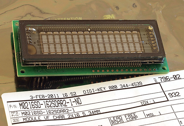
its pretty much plug and play! I made some minor adapting from my lcd edge connector so that pin3 for contrast is 'open' and pins 15,16 are also 'open':
and that keeps the backlight on the controller from doing anything on the lcd as well as that contrast pot pin (that normally should be N/C but just in case, its REALLY a N/C now).
power it up and it says hello
to be really complete, you should have some way for the controller to know if its lcd or vfd and if its vfd, send 4 levels of brightness on the bottom 2 bits of a special control byte, you send over the 4 bit interface. if its lcd, you vary the pwm output to pins 15,16. but if you don't care about brightness, then this should just power on and work as-is.
(tested on my own controller; no idea about the ebay one but I'm not planning on using the ebay controller; just the ebay vol control engine/board and interfacing my controller to that).
AMB Laboratories DIY Audio • View topic - VFD display experiment
its pretty much plug and play! I made some minor adapting from my lcd edge connector so that pin3 for contrast is 'open' and pins 15,16 are also 'open':
and that keeps the backlight on the controller from doing anything on the lcd as well as that contrast pot pin (that normally should be N/C but just in case, its REALLY a N/C now).
power it up and it says hello
An externally hosted image should be here but it was not working when we last tested it.
to be really complete, you should have some way for the controller to know if its lcd or vfd and if its vfd, send 4 levels of brightness on the bottom 2 bits of a special control byte, you send over the 4 bit interface. if its lcd, you vary the pwm output to pins 15,16. but if you don't care about brightness, then this should just power on and work as-is.
(tested on my own controller; no idea about the ebay one but I'm not planning on using the ebay controller; just the ebay vol control engine/board and interfacing my controller to that).
6 ch volume control e-bay
Anybody familiar with this 6-ch volume control? Looks like it may work with 2 or 3 way active crossovers (such as DCX).
6Way M62446 5.1 Volume Remote Control Preamplifier Kit - eBay (item 260706403227 end time Feb-08-11 20:21:36 PST)
Anybody familiar with this 6-ch volume control? Looks like it may work with 2 or 3 way active crossovers (such as DCX).
6Way M62446 5.1 Volume Remote Control Preamplifier Kit - eBay (item 260706403227 end time Feb-08-11 20:21:36 PST)
I can't tell what chip that uses for vol control on that ebay board.
and like us, you will get little support and probably the wrong or outdated schematic ;(
also, the pcb layouts on these cheap chinese boards are really BAD. no decent ground planing, inputs near outputs or inputs near clock sources, bypass caps too far away from chips, etc. just really a bad effort overall. and depending on how mean the seller/maker is, they can even SCRATCH OFF CHIP MARKINGS on chips before selling to you. you can't know what the chip is or even if its fake. want to replace it later? good luck. ;(
also note, the ribbon cable is probably where your analog-out goes (!). does that look audio grade to you? not me.
I got my kit knowing it would be a test bed for me but not to use in real life. afterI got my kit, looking at the really bad trace layout and design of the board, I still feel it would not be suitable for use in anything but a kid's first stereo set. not really audiophile grade, imho.
almost every time I buy from china, I regret it for one reason or another; so I can't really recommend using these systems as-is. heavily modified, maybe they will be ok.
Last edited:
I have just finished this temporary kit.... very disapointed.
sound loose a lot of detail. sound is more detailed on my Dac Zero using the integrated preamplifier (that don't use a HDAM on this stage) than Direct RCA output using HDAM and with this kit.
LCD display is a real bad choice. White text on a blue background, at 2 meter I can't read it, nothing compared to my DIY CD transport with VFD display.
Will wait for LCDuino (or VFDuino) and a good PCB board for the PGA2311 to use with.
Tend to agree that e-baying from China is a high risk. Anyway I ordered one so let's see what comes. Indeed it doesn't say which volume chip is used. The output opamps are NE5532 (luckily easily replacable, probably with LM4562's), I see the tantalum bypass caps fairly close....
I will post information here once I receive it.... Worst case, like you said: goes to kid's room. But let's see first.
I will post information here once I receive it.... Worst case, like you said: goes to kid's room. But let's see first.
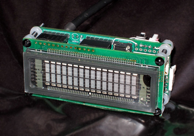
more good success today with that damned thirty dollar vfd (lol)
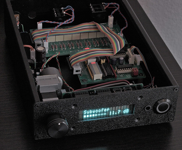
I just dropped it in, after removing my old 'classic' lcd. its not mounted but the same screw holes (on 16x2) should work - that's kind of the whole point of a drop-in
I have not tested the audio path yet. no idea if a metal shield is needed or useful or ferrites or what. I just 'dropped it in' and at least at the logical level, it works. the same exact lcd routines I used to write to lcd's also seem to work unchanged, even with the bargraph graphics. no brightness control on unmod'd firmware but I plan to add the 2bits of levels and some way to config the thing (at install time) to tell it to treat it as an lcd or a vfd.
it also draws hundreds of ma. my regulator is getting warm now (7805). be aware of this.
I still think it might be good to have a 7805 just for this display and then 7805 for the arduino/rest of system. maybe overkill but it seems like a proper design decision unless we find its really totally not necessary.
there is also burn-in with vfd's. the spec sheets even mention that. so a screen saver is needed or an auto turn-off after non-use. I have that working in my lcd-based code (display can optionally fade off after 4 secs or so of non-IR or knob use) but I have yet to add that code for vfd's.
this color seems to match the logitech squeezebox (I have an SB3) and for that, I'm kind of happy. this new box will probably sit right next to the SB3 and so the colors and style will match, at least on the display parts.
Tend to agree that e-baying from China is a high risk. Anyway I ordered one so let's see what comes. Indeed it doesn't say which volume chip is used. The output opamps are NE5532 (luckily easily replacable, probably with LM4562's), I see the tantalum bypass caps fairly close....
I will post information here once I receive it.... Worst case, like you said: goes to kid's room. But let's see first.
there is no photo of the vol chip. I wonder... maybe its the surface mount version and its under the board. hope its not some 'wonder chip' with scratched off markings ;(
I have just finished this temporary kit.... very disapointed.
sound loose a lot of detail. sound is more detailed on my Dac Zero using the integrated preamplifier (that don't use a HDAM on this stage)
I will take some photos of the bare board (the audio board, I don't care at all about his wacky controller backpack. that's a throw-away to me).
maybe I'm being harsh, but it looks like an idiot designed this board (that I got; the 6channel version). you can look at crystal or burr-brown and see their recommended ground planing and separation of digi and analog gnds. this guy who did the board I got followed NONE of that. deep sigh. where do they get off putting out such crappy products?
I'm glad I never intended to actually *use* this; I really just wanted a test-bed so I can write software for it, in general, before my own PGA board even gets built. to software, if the chip ACKS, you're golden (lol). the quality of the audio path does not matter - you can put mp3's in one end and if the volume varies out the other end, software is happy. but its sad that that's ALL it will be - a dev platform and not worthy of being depoyed in actual product. quite sad.
...maybe I'm being harsh, but it looks like an idiot designed this board (that I got; the 6channel version)....
Yes. You have been spoiled with AMB's superb craftmanship...
I only have the y1 board from AMB and I'm really impressed at the layout and workmanship.
Tend to agree that e-baying from China is a high risk....
Well, you get what you see
. I took a look at the photos in ebay and I would agree with linuxworks: lack of gnd plane, bypass caps far away, etc. Not a "serious" design, but it is all there for you to see...I have just finished this temporary kit.... very disapointed.
sound loose a lot of detail. sound is more detailed on my Dac Zero using the integrated preamplifier (that don't use a HDAM on this stage) than Direct RCA output using HDAM and with this kit.
LCD display is a real bad choice. White text on a blue background, at 2 meter I can't read it, nothing compared to my DIY CD transport with VFD display.
Will wait for LCDuino (or VFDuino) and a good PCB board for the PGA2311 to use with.
LCDs are very finicky with the contrast control. I don't know if your kit comes with an adjustment pot... I also like VFD displays but don't look good "naked". I put them behind a tinted glass/plastic. You can pick up a piece of tinting material from car shops and apply it to a piece of plastic or glass.
If your kit looks like the ones in the ebay pictures, some simple mods will improve the kit a lot: bypass caps at the pins, inputs and outputs at the dip holes connections next to the chip.
[I'm not trying to make excuses for the vendor, but now that you have it, might as well make the most out of it
]in fact, I was going to air-wire some local bypass caps (electrolytic and .1 of some kind, maybe film if I'm in the mood, lol) to each of the PGA chips. there are relays there that I may just jumper over (not that they hurt but i don't plan on using their input selector part). the power supply is dual 78xx/79xx and I'm thinking an offboard 317/337 would be a step up in quality.
on my board, they use a 10ohm R to separate digital + from analog + but I'd like to upgrade that to a ferrite at the very least.
the ins and outs (traces) are going all over the place so I'd airwire some jumper wire from the traces near the pins and put lots of twists on the wire pairs for better shielding.
also keep the clock/chipselect/data crap (lol) away from the analog stuff!
I think the board will work, electrically, but I'm not surprised its not great for clean sounding audio.
another pga kit that comes to mind is this one that I found a few years ago doing a remote-control search:
IRVC2 remote volume control with LCD
his is also NOT open source but I have more confidence in the layout on his. I would do the same thing: use his board as the engine and use another controller that is open source instead of his.
linuxworks,
I have also been looking at the IRVC2 remote volume control with LCD
It has way to many inputs for me, but I really like the way he uses any remote (I can use my original Sony TV remote)
I talked to him about the IRVC, but I have decided to get the IRVC2 because the PGA chip(s) are on the same board to cut down on the clutter.
Alan
the learning remote is a feature my code also has. its a nice feature that lets you go thru a dialog at config-time and store codes from any remote.
on mine, you press a config button within the first few seconds of power on and it goes thru a dialog: "press the up-arrow key" then "press down-arrow" and so on. after you hit each key as prompted, it saves the results in eeprom and stays until/unless you re-do the config.
the tauntek guy will not release his source, either (I asked him once a few yrs ago). so while it might be an ok board, you had better like the firmware as-is since you won't get any updates or changes.
Check out the minivol, to see if you can integrate it into your
design. The analog and digital grounds are properly separated
and the PCB is really tiny.
MiniVol PGA2320 Volume Control - error404's Audio DIY Endeavours
I built a quick-n-dirty prototype remote controlled channel
selector and volume control using the MiniVol board and it sounds
excellent. It works great using a cheap ebay 4 channel RF
remote (nice and small, like a car keyfob remote).
http://www.diyaudio.com/forums/anal...rf-controled-pga2320-minivol-ch-selector.html
error404's minivol board works! I also hacked it to have it be arduino controlled instead of the small onboard controller. his layout was good and he followed the basic pga designs. 'showing up is 90% of it' as they say
is he still selling them? it seemed that he was not 'doing' them aymore last time I asked.
is he still selling them? it seemed that he was not 'doing' them aymore last time I asked.
- Status
- This old topic is closed. If you want to reopen this topic, contact a moderator using the "Report Post" button.
- Home
- Source & Line
- Analog Line Level
- volume remote control module with PGA 2311