Interesting. Not much difference.
you know that you can load two measure sets in RMAA and show both on the graphs. Helps to visually compare 😉
you know that you can load two measure sets in RMAA and show both on the graphs. Helps to visually compare 😉
is it possible to set the atten at a few other levels (on the pga) and then do the rmaa?
i wonder how noise and distortion change as you ask the pga to vary its atten range and even more so, what happens once you go into the + range and get actual gain from its internal op-amp.
I was not disappointed, overall, with the pga boards I tried but once you got over 0 db, the noise level did go up audibly.
I loved having the gain, though. at the time I was using a media streamer that had some 'movie mode audio bug' that would play 5.1dd/dts movies about 10db lower than they should have, when downmixed to 2.0. I needed and extra 10 of gain just to watch movies and hear the sound, and a pure attenuate-only control would not go high enough. yes, the media streamer was at fault, but still, it was nice having the 'above zero' gain for when it was needed.
Hi,
Apart from the crosstalk (high end definition muddied by digital noise ?), the tests just show this volume control is performing at least on a par and potentially better than the sound card. I need better gear and better knowledge of the software to really test this thing.
And while the numbers are nice to know, to be honest, I'm far more concerned with real listening tests. Add in my time restrictions and, well, sorry, but that's it for me. Someone else's turn..... ;-)
For sure, I'm happy that this baby is good enough for the AV role it'll play.
Tom
I have the beginning of a test bed:
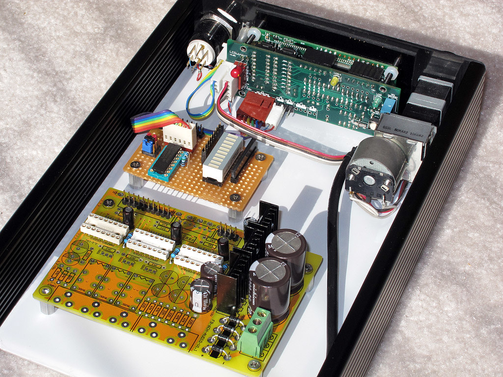
this is a 6 channel (3 PGA chips) ebay board that I'll use to test out my code and interface. the perf board is something I made last nite that will interface i2c down to bit-banged SPI (for the PGA). I have headers on my board and placed headers on the PGA board. now I have to make an adapter ribbon to map my bit definitions to the ones the PGA board expects. after that its a matter of connecting the analog in's and out's from patch points on the board to my rear jacks (not shown).
the case and lcd unit were from a previous build, so I saved a lot of effort on that. I installed this test bed of guts on a slide-out piece of plexiglass (still with white paper backing on it). it was easy to lay that on the case, lay the boards on top, mark wtih pencil and drill holes. very cheap and dirty for rapid prototyping and it keeps things in place. when I want to work on it, I slide the whole bottom layer out and work on it out of the case.
I was able to see lights on my LED strip blink 'as they should' when I turn the volume knob on my software. I have had this working in the past and so I think the software will still work today. I used the following bits:
bit0: common SPI clock
bit1: common SPI data
bit2: chip-select PGA-0
bit3: chip-select PGA-1
bit4: chip-select PGA-2
bit5: common MUTE
previously, I've always hard-wired mute to + and left it there, then just used software zeroes to mute the thing; but I had a spare bit in PE so might as well export it. I'll probabaly always OR in the ~MUTE bit as a 1 but at least if I want to play with it, the bit is there.
perhaps today I'll finish wiring this and give it a test run. laying down the phys infrastructure is never really the fun part, for me 😉 I put it off as long as I can; but if there's no infrastructure, there's no test bed and therefore, no software can be developed/tested.
update: it works!
only 1 chip is wired in right now but the software works and so does the board.
I can't comment on audio quality but that was never my purpose with this kit. I did avoid installing the front end resistors, caps, relays and driver transistors. input selection is happening in another module, not here.
so, proof of concept is complete. volumaster (my software for the arduino) is updated to include the PGA driver. if you want to use it you will have to build the i2c port adapter or patch the code to use direct arduino pins, if you want to go direct SPI (nothing wrong with that but I prefer i2c for universal and 'remotable' control).
Nice! this is exactly the implementation of the LCDuino I'm planning, is there a way to implement individual volume control, say for bi and tri-amping aplications?
right now, there's no provision at all for varying volume out of the 'gang' relationship. to do balance or fade and do it even somewhat well would mean another 500 bytes or more of code and I can't easily find that. yes, its that tight (out of about 30k of actual machine code). I've spent some time breaking things into 'ifdef' bundles so that people can choose which options to omit in order to be able to build AND load the image to the cpu.
once you hit a wall like that, I can't think of any other way than to give people choices at build time. for example, it takes a lot more code to support non-sony IR remotes and by removing nec/rc5/rc6, you gain at least another 500 bytes. really valuable room! seriously. so I can disable non-sony IR style remotes, choose to use a sony-device mode on some multibrand remote and be able to unlock a bunch of other goodies that I do want to have onboard. others may want full multibrand remote support and so would not be able to have relay and pga support, for example. or no spdif switch and d2 switch support. or remote bigfonts support.
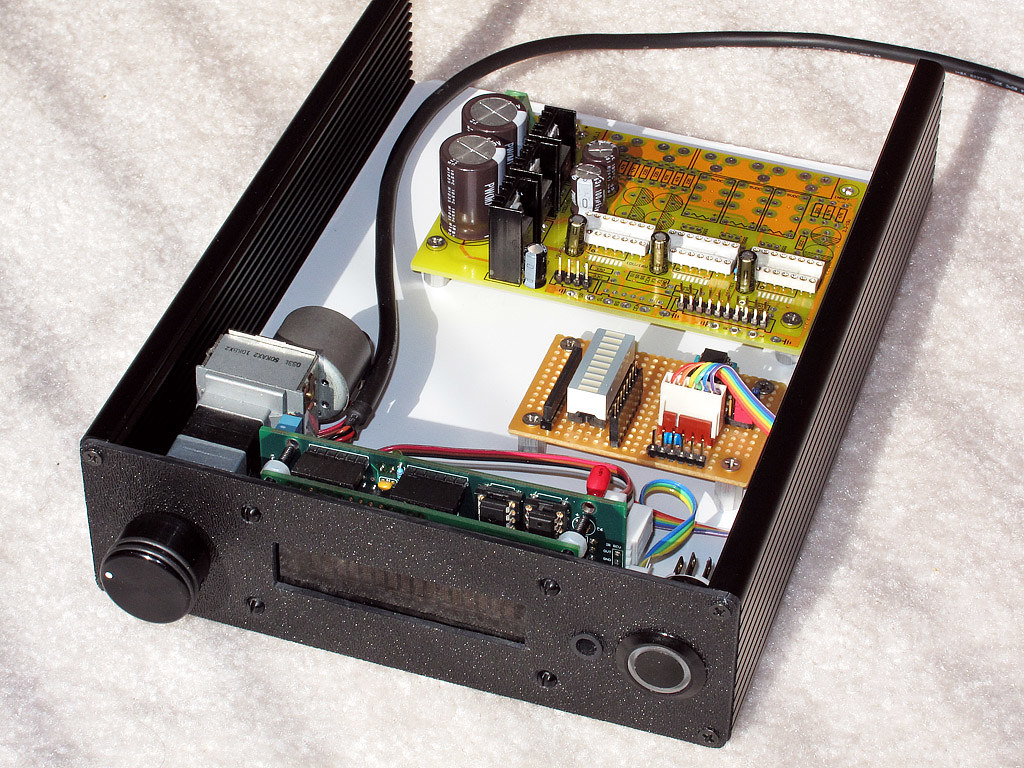
back to my testbed, I wired up the other 2 channels (in my build) and they work, now, too. there's also a pic of the 'old shell' that was a single board stereo 127db relay atten and the new shell that is the PGA engine - but using the same exact face and cpu and code! I really wanted to have some pluggable vol engine support and I got it. also pluggable i/o selector support, for delta2 relay based OR 2 kinds of spdif/other switch (addr and bitmap modes on a port expander; that would select 1-of-n fabric for spdif or anything else you want). you can mix/match, too; pick pga for vol and spdif for i/o or pick d1 for vol and spdif for i/o, but only 1 from columnA and one from columnB (lol).
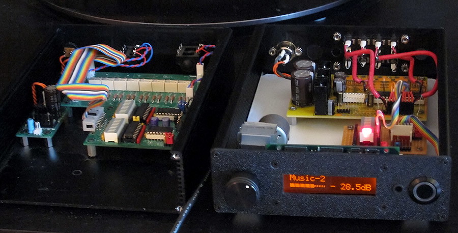
very blurry handheld snapshot but the light was fading and I really hate using flash. (I also hate using camera flash, too. lol)
once you hit a wall like that, I can't think of any other way than to give people choices at build time. for example, it takes a lot more code to support non-sony IR remotes and by removing nec/rc5/rc6, you gain at least another 500 bytes. really valuable room! seriously. so I can disable non-sony IR style remotes, choose to use a sony-device mode on some multibrand remote and be able to unlock a bunch of other goodies that I do want to have onboard. others may want full multibrand remote support and so would not be able to have relay and pga support, for example. or no spdif switch and d2 switch support. or remote bigfonts support.
back to my testbed, I wired up the other 2 channels (in my build) and they work, now, too. there's also a pic of the 'old shell' that was a single board stereo 127db relay atten and the new shell that is the PGA engine - but using the same exact face and cpu and code! I really wanted to have some pluggable vol engine support and I got it. also pluggable i/o selector support, for delta2 relay based OR 2 kinds of spdif/other switch (addr and bitmap modes on a port expander; that would select 1-of-n fabric for spdif or anything else you want). you can mix/match, too; pick pga for vol and spdif for i/o or pick d1 for vol and spdif for i/o, but only 1 from columnA and one from columnB (lol).
very blurry handheld snapshot but the light was fading and I really hate using flash. (I also hate using camera flash, too. lol)
to properly answer the question, I think a combo of BOTH relays and a silent PGA would be idea. I think I'm going to do that.
with relays, you can pick your resolution. for 'balancing' or matching, i want a lot more than half-db. on the pga, you can only go down to a half, from one thing to the next. its there for completeness but I don't see any hifi use in it, to be honest.
what I want to solve this is what I call a 'trimmer box'. that device is there to normalize things and you'd have one on each amp's input, for example. those things are not full range vol controls but maybe only 20 or 30 db range (if even that) but carve those slots up into tinier pieces. the relays can do this extremely well and with high accuracy and pretty low cost, too. I did an 8bit tenth-db (25.5db max) build and it was meant as a subwoofer 'trimmer box'.
the neat thing about trimmer boxes is that you do NOT actively vary them. you set them, calibrate them if you will, then leave them alone.
with these latching relays, you could, in theory, bury a relay module IN your amps, 'calibrate' it and then remove both the controller and power from it. it will retain its last state until told otherwise. ie, never 😉 its passive and just 'runs' after its set. ideal for a trimmer!
I could envision a whole set of amps and speakers and each one having a trimmer module and a 'management port' that you connect to, one by one, calibrate and then move onto the next. I've never seen this done before and it might be a brand new idea, in fact. but its removing a 'calibration part' and saving cost and space along the way. just an idea..
anyway, the pga ganged volume pot would always move in unison and any downstream trimmer would adjust that 'common level' to whatever the subentity needs. the relays never move in vol-up/down operation and they never need power. the pga's move but they never make relay clicking.
win/win.
but you need 2 levels of box. toplevel and a bunch of sublevel trimmers.
would having several lcduinos running off of a common pot for master volume, and having several pots run off of its wiper for individual control? One main screen on the master of course.
you could series-run these. in fact, that's the whole idea on the distributed 'main vs trimmer' topology.
the top guy could be a relay guy or pga or regular analog control. the ones below could also be various technologies.
what I thought was key is that the lower ones offer very fine db resolution and ideally, they should be set-and-forget so they stay out of your way.
you could have a pga on top with 3 chips (like my board) and run 3 sets of stereo outs (tri-amp processed from a crossover). then those 3 sets would go to 3 trimmer boxes or one big box with 3 trimmer setups in it.
a custom version could be made that sets the offset level on each 'board' and leaves it there. that would be the cpu that talks to the trimmers.
the main vol cpu and display would not know or care of the eixstence of any downstream boxes. its ONLY job is to vary all 6 channels in sync and give the user half db up/down incrs. the daily use knob.
you could use ldr's downstream if you configure them for fine steps. or even motor pots 😉 whatever you want. but I do think the notion of trimmer is separate (when its a multi amp config) from the main vol attenuator.
Nice job ! Looks much better than mine ;-)
You were right about the noise above 0dB. As soon as the chip goes into gain the noise ramps up dramatically; from normal snr to audibly hissy. Horrible.
The other thing I've found is that there seems to be some noise-decay (noise like the ticking of a clock) when the signal is suddenly interrupted at high gain. I get a slight thock-thock-thock that decays to nothing very rapidly. It's very quiet but audible at high gain. This is nothing to do with changing settings. It's simply the source being paused. I wonder if it might be the source and volume control interacting in a weird way, or if it is the PGA itself turning itself down to control offset or something, and that digital noise is getting into the analogue cos of the poor PCB.
Anyway, the chip does a good job up to 0dB. It's only above 0dB when it is a poor performer. So if anyone needs gain, use a separate op amp as this chip is dire for gain.
Also, I forgot to mention, the relays in the kit took a tap to get them to work initially, but have worked flawlessly since. So upgrading them might be worthwhile.
I had a Mini years ago that had the same fault on the starter solenoid. To my friends great amusement, I used to have to open up the hood/bonnet and hit it with a tap hammer to get the ignition to switch on. Not funny with electronics though.
Tom
I hear the ticking as you go above 0db into gain but only when you vary thing. once you leave the knob alone things are ok.
maybe you have dc offset coming thru? or not good (perfect) grounding?
if you are using the controller that came with the ebay toy, that could also be kicking back junk into the psu. my board had the luxury of having a private 7805 for the cpu and a set of 7805/7905 for the pga analog/digital path. if yours does not have a cpu regulator, maybe try that. and play with grounds.
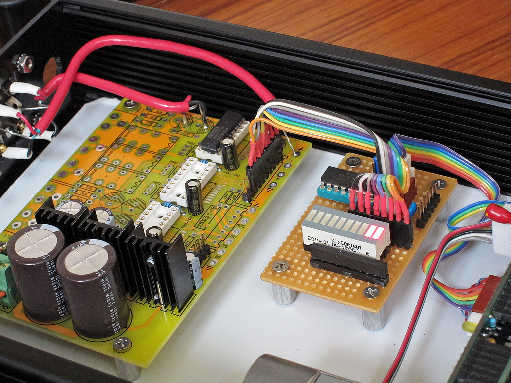
pic of my perf-board port expander:
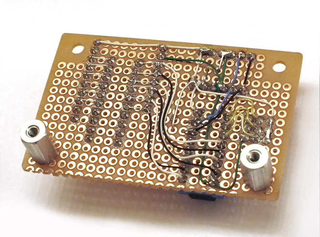
took me a few hours to build that. its essentially half of a delta1 controller, just 1 port expander chip, some debug led segments and address jumpers.
I added a 2nd i2c set of headers as a pass-thru port. in case you want to daisy chain a switch or some other i2c controlled device to this.
took me a few hours to build that. its essentially half of a delta1 controller, just 1 port expander chip, some debug led segments and address jumpers.
I added a 2nd i2c set of headers as a pass-thru port. in case you want to daisy chain a switch or some other i2c controlled device to this.
I hear the ticking as you go above 0db into gain but only when you vary thing. once you leave the knob alone things are ok.
maybe you have dc offset coming thru? or not good (perfect) grounding?
if you are using the controller that came with the ebay toy, that could also be kicking back junk into the psu. my board had the luxury of having a private 7805 for the cpu and a set of 7805/7905 for the pga analog/digital path. if yours does not have a cpu regulator, maybe try that. and play with grounds.
Hi,
No offset and the grounding is starred so I'm going with mcu noise and/or needing independent grounding.
cheers
Hi,
No offset and the grounding is starred so I'm going with mcu noise and/or needing independent grounding.
cheers
Sounds like a grounding or offset issue to me.
BTW, Linuxworks, which port expander chip did you use, and how did you wire it up? I'm new to this sort of digital business.
pcf8574. I'm using those a lot since they are multi sourced, cheap, fast and don't have too bad a layout. no chip overhead; each byte over i2c is the byte you get. no setups needed, like the mcp chips need.
pinout is data sheet. or use this for a ref:
AMB Laboratories DIY Audio • View topic - ?1 links
and this
The LCDuino-1 I/O processor - Page 23 - Head-Fi.org Community
the schematic for the delta1 and 2 use the same controller.
my bargraph shows amazing similarity (lol) and is exactly half that controller, minus the relay driver ULN chip.
you can bit-bang over i2c well enough. that means you send an i2c *message* for each BIT you want to change. when you send the typical dialog, chip-select, data, clock, data, clock - each of those is a bit 'wiggle' and that means an i2c byte is sent over. the byte is the new bitmask and you just replace old values with new values. if a bit does not change, you send its old value and it never 'bounces' until and unless you send a new bit value in the mask, to the PE.
Code:
void
pga2311_set_volume (byte left, byte right)
{


    // strobe chip-select
    pcf.write(6, PGA_I2C_CS_HI | PGA_I2C_MUTE_HIGH);        // start from high (logical-NOT on chip-select)
    pcf.write(6, PGA_I2C_CS_LOW | PGA_I2C_MUTE_HIGH);       // begin getting the chip's attention

    // write 2 bytes of data
    pga23xx_write(left);                      // left value (0..255)
    pga23xx_write(right);	              // right value (0..255)

    // unstrobe chip-select
    pcf.write(6, PGA_I2C_CS_HI | PGA_I2C_MUTE_HIGH);
  return;
}


void
pga23xx_write (byte out_byte)
{
  int i;

#ifdef DEBUG_PGA
  Serial.print("PGA:");
  Serial.println((int)out_byte);
#endif


  // loop thru each of the 8-bits in the byte
  for (i=0; i < 8; i++) {

    // strobe clock
    pcf.write(6, (PGA_I2C_CS_LOW | PGA_I2C_SCK_LOW | PGA_I2C_SDATA_LOW | PGA_I2C_MUTE_HIGH) );

    // send the data_bit (we look at the high order bit and 'print' that to the remote device)
    if (0x80 & out_byte) {  // MSB is set
      pcf.write(6, (PGA_I2C_CS_LOW | PGA_I2C_SCK_LOW | PGA_I2C_SDATA_HI | PGA_I2C_MUTE_HIGH) );

    } else {
      pcf.write(6, (PGA_I2C_CS_LOW | PGA_I2C_SCK_LOW | PGA_I2C_SDATA_LOW | PGA_I2C_MUTE_HIGH)) ;
    }


    // unstrobe the clock
    if (0x80 & out_byte) {  // MSB is set
      pcf.write(6, (PGA_I2C_CS_LOW | PGA_I2C_SCK_HI | PGA_I2C_SDATA_HI | PGA_I2C_MUTE_HIGH) );
    } else {
      pcf.write(6, (PGA_I2C_CS_LOW | PGA_I2C_SCK_HI | PGA_I2C_SDATA_LOW | PGA_I2C_MUTE_HIGH) );
    }


    // get the next bit
    out_byte <<= 1;   // left-shift the byte by 1 bit
  }

  return;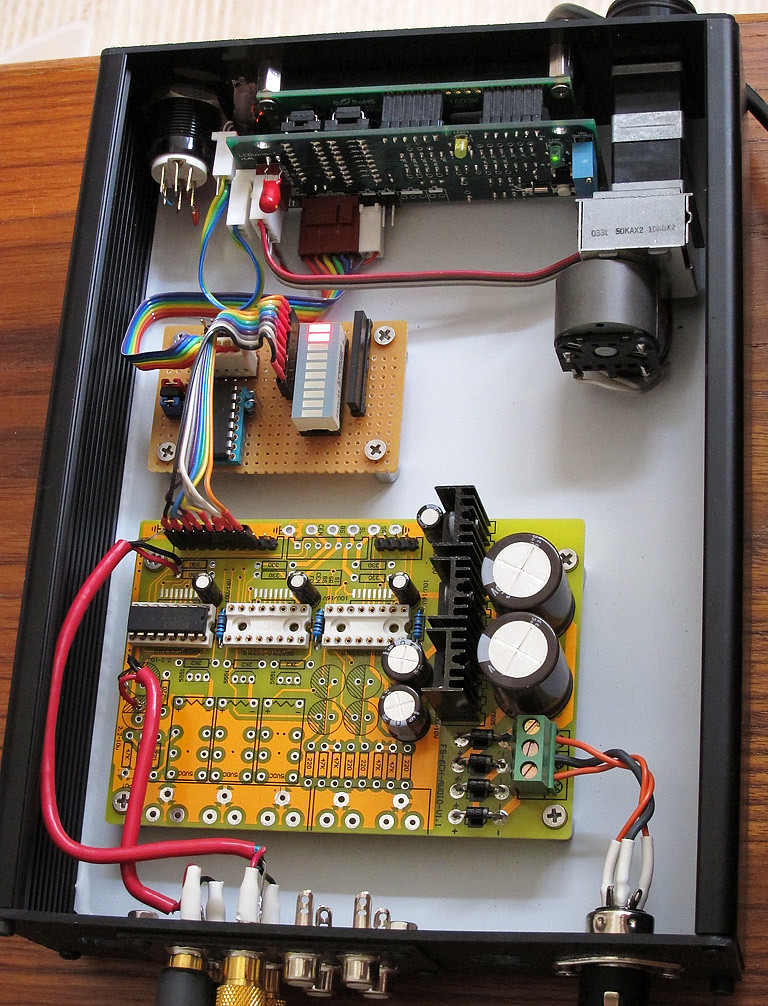
}better photo of the current test bed. 4 channels (out of 6) are wired up. and chipped up, too, I guess 😉
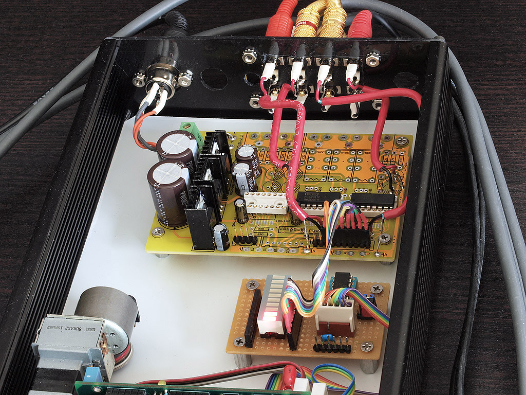
the box is just too small to do 4 more rca's on the back. right now, I have my dcx2496 splitting into 2-way with my subwoofer taking the LP and my tannoys taking what's above it. this 2-way volume control works fine for that. and I don't feel like redoing the back plastic work - it was already a re-use of a previous project 😉
2 chips seem to be working ok. I have not tried the 3rd yet and I've recently seen an ebayer (I think the only one with this board) show this board with a wire on the back and it looked like it was going toward the 3rd chip. maybe that's the time bomb (lol) that I haven't come across yet. maybe I'll stop at 2 and consider myself lucky.
I really hate the layout of this board. digital signal real close to analog ones; no groundplaning at all near the sensitive chips, no bypassing other than a SINGLE electrolytic, just not much good to say other than it does electrically work and lets a software guy play around 😉 I would not deploy this kind of board in production, though. its a POS. but for software, even POS is fine (lol).
today, AMB (my co-design partner) and I did an rmaa on this box. we were both surprised. "its clean" 😉
I'll post a link to the rmaa results but IIRC, the noise was down something like 100db or more. definitely 'clean and quiet' for most ears. even with this 'badly laid out' PGA board, we were getting very decent specs at 0db and even 3db (yes, with gain). not much distortion, IM or anything bad. this is without even doing the 'required' bypassing that BB and cirrus recommend.
so I guess this 'test bed' is actually quite a bit more. its almost production sound quality 😉
leaving out the caps and the level shifting resistors was not a bad idea. leaving out the relays also didn't hurt (I've heard these are really cheap relays that ship with this kit).
Very nice, i've been thinking of designing a board for this chip that has room for decent caps and utilises proper grounding, nice to know even a sub-standard pcb can give good results.
surprised the hell out of me, it did 😉
by all accounts, it should suck. and yet it did not. I will repeat the rmaa test but once we got windows to finally see the firewire audio (test) box, its test run showed really nice results.
I think its easy enough to upgrade the 7805 series chips to 317, at the very least. it can't hurt. and proper bypass (electro AND a .1 of some kind) should also be done. again, I can't imagine it would hurt and could only help.
I did use all my own parts, though. I used the board from ebay but skipped using his caps, his chips and his sockets. I will try his chips later on and see if they test any differently, but I wanted to use known good chips, first, to at least give this critter a fighting chance.
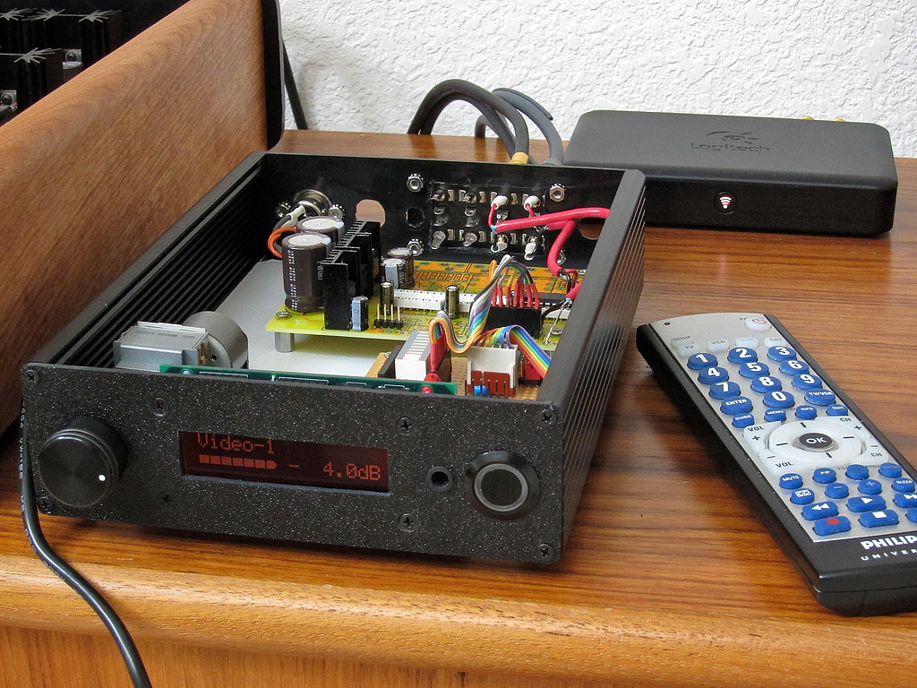
as I posted on a 'digital line level' thread, I also have my DIY spdif switch integrated with this entire system:
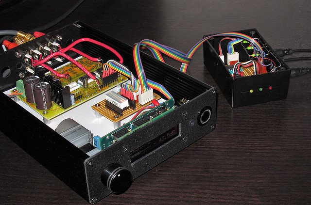
the 'pod' on the right is a collection of 3 toslink inputs and 1 toslink output. you go into the LCD menu, select 'spdif' as the i/o engine and whammo - your input ports now do spdif routing on that remote pod. locate the pod near your dac or other digital things and connect the pod to the front-facing lcd/ir box via an i2c cable. details to be worked out later as to connector types, but I'm thinking of overloading the firewire (6pin) connector and that gets me pre-made easy and cheap cables and less soldering for me to worry about 😉 there should be enough 'specs' in the firewire cable to carry my i2c connection of clock+data+power over to the pod box.
this is what I'm using now as my main audio/video system. this little box and its pod have replaced my previous AVR. (note, I don't do multichannel at home; I downmix all my movies to 2.0 so that they are spdif compliant and not dd or dts stuff). when I select 1 input, it picks the right spdif port and also adjusts volume to that port's last used setting. switch to another port and you get the spdif-feed from my HTPC or media streamer and it corrects the volume to last-set value for that port, etc.
I have a hack for linking in an hdmi switch, too; but more about that later.
by all accounts, it should suck. and yet it did not. I will repeat the rmaa test but once we got windows to finally see the firewire audio (test) box, its test run showed really nice results.
I think its easy enough to upgrade the 7805 series chips to 317, at the very least. it can't hurt. and proper bypass (electro AND a .1 of some kind) should also be done. again, I can't imagine it would hurt and could only help.
I did use all my own parts, though. I used the board from ebay but skipped using his caps, his chips and his sockets. I will try his chips later on and see if they test any differently, but I wanted to use known good chips, first, to at least give this critter a fighting chance.
as I posted on a 'digital line level' thread, I also have my DIY spdif switch integrated with this entire system:
the 'pod' on the right is a collection of 3 toslink inputs and 1 toslink output. you go into the LCD menu, select 'spdif' as the i/o engine and whammo - your input ports now do spdif routing on that remote pod. locate the pod near your dac or other digital things and connect the pod to the front-facing lcd/ir box via an i2c cable. details to be worked out later as to connector types, but I'm thinking of overloading the firewire (6pin) connector and that gets me pre-made easy and cheap cables and less soldering for me to worry about 😉 there should be enough 'specs' in the firewire cable to carry my i2c connection of clock+data+power over to the pod box.
this is what I'm using now as my main audio/video system. this little box and its pod have replaced my previous AVR. (note, I don't do multichannel at home; I downmix all my movies to 2.0 so that they are spdif compliant and not dd or dts stuff). when I select 1 input, it picks the right spdif port and also adjusts volume to that port's last used setting. switch to another port and you get the spdif-feed from my HTPC or media streamer and it corrects the volume to last-set value for that port, etc.
I have a hack for linking in an hdmi switch, too; but more about that later.
- Status
- Not open for further replies.
- Home
- Source & Line
- Analog Line Level
- volume remote control module with PGA 2311