the learning remote is a feature my code also has. its a nice feature that lets you go thru a dialog at config-time and store codes from any remote.
on mine, you press a config button within the first few seconds of power on and it goes thru a dialog: "press the up-arrow key" then "press down-arrow" and so on. after you hit each key as prompted, it saves the results in eeprom and stays until/unless you re-do the config.
the tauntek guy will not release his source, either (I asked him once a few yrs ago). so while it might be an ok board, you had better like the firmware as-is since you won't get any updates or changes.
Is there any "open-source" options that is similar?
Thanks
By the way,
I checked out your flicker feed and you got some great projects.
It was interesting to read about the netbook hackintosh.
I didn't realize how easy it was for some netbooks.
my project will have its source released. working on it now, getting real close to release as it is.
GLT also has a lot of arduino source for hi-fi things.
the minivol was open source, too, but it was rotary encoder, only, no IR and no display.
the source based ones are definitely in the minority, that's for sure. I have not found a single chinese based one that is open source. in fact, its common to scratch numbers off chips, so I would never expect the imports to have opensource on software. it seems they like to take but not give ;(
my project will have its source released. working on it now, getting real close to release as it is.
Can you tell us what features your project will have?
Thanks,
there's a lot to read about ")
start here, perhaps: AMB Laboratories DIY Audio • View forum - LCDuino System
a working example is the 'a10 preamp' on amb's site; that gives a general idea although it does not talk too much about the software, just the hardware.
I think there are some unique features, such as x10 'firecracker' remote support: this is the x10 powerline on/off switches and I've integrated code so that you can turn amps on and off with no wire mess (nice for sleep timer, lol). it has a learning Ir remote on the receive side, user settable port names, up to 8 ports on the i/o board that you can 'punch down' to either input bus or output bus, there is a unique window control ('clip window') that lets you define the min volume and max volume on a linear track pot and the volume stays inside that range (plus the pot has full travel in that narrowed down range). user defined brightness levels, user defined mute levels, last-remembered vol for each input/output path, new support for lcd/vfd, realtime clock/calendar with battery backup, support for various lcd sizes (2x16, 2x20, 4x20), front panel 'resistor buttons' for alternate input to IR remote. those are the highlights that come to mind but I'm sure I forgot quite a few.
there's a lot to read about
start here, perhaps: AMB Laboratories DIY Audio • View forum - LCDuino System
a working example is the 'a10 preamp' on amb's site; that gives a general idea although it does not talk too much about the software, just the hardware.
I think there are some unique features, such as x10 'firecracker' remote support: this is the x10 powerline on/off switches and I've integrated code so that you can turn amps on and off with no wire mess (nice for sleep timer, lol). it has a learning Ir remote on the receive side, user settable port names, up to 8 ports on the i/o board that you can 'punch down' to either input bus or output bus, there is a unique window control ('clip window') that lets you define the min volume and max volume on a linear track pot and the volume stays inside that range (plus the pot has full travel in that narrowed down range). user defined brightness levels, user defined mute levels, last-remembered vol for each input/output path, new support for lcd/vfd, realtime clock/calendar with battery backup, support for various lcd sizes (2x16, 2x20, 4x20), front panel 'resistor buttons' for alternate input to IR remote. those are the highlights that come to mind but I'm sure I forgot quite a few.
Sounds like it is going to be sweet!
I can't wait.
Thanks for the details...
6-ch volume
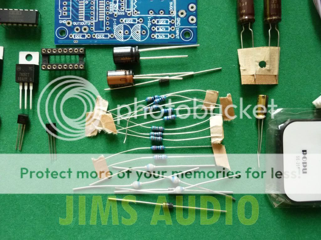
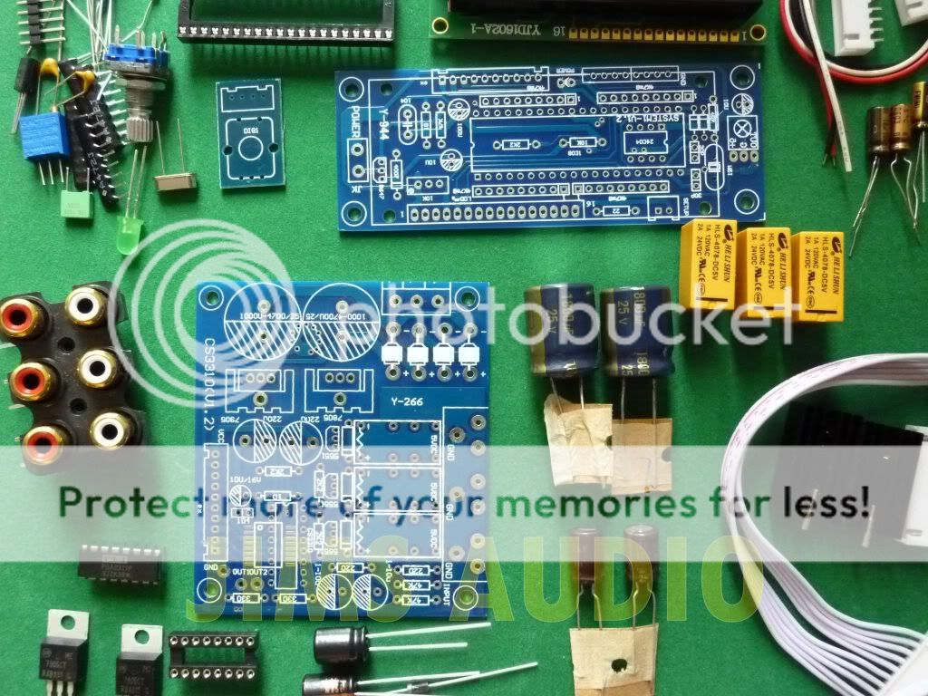
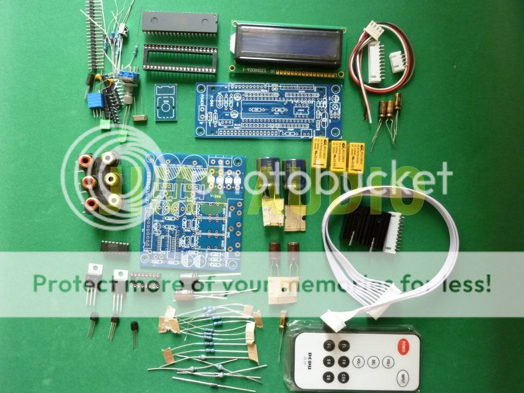
Received the product (as per link posted in post #25, page #3).
The boards are not bad at all, nicely made, dual-sided, clean, Elna and Nichicon caps, TI 5532Ps, tantalum bypass caps.
What's not visible on the pictures is the volume chip (on the bottom side): it is Mitsubishi M62446FP.
Did not connect yet. Hope it works.
Hey Draki,
Let us know how well that 6 channel volume control works - I'm very curious ! Do the tone controls work ? The specs don't seem as good for Mitsubishi chip as the Ti PGA2311 but specs never tell the whole story eh ?
Anyone come up with better firmware for the PGA ?
cheers
Let us know how well that 6 channel volume control works - I'm very curious ! Do the tone controls work ? The specs don't seem as good for Mitsubishi chip as the Ti PGA2311 but specs never tell the whole story eh ?
Anyone come up with better firmware for the PGA ?
cheers
Last edited:
I tried the 6ch-VC for a brief period only (one hour or so)- mainly to check the inputs/outputs. The 6VC works OK, no noise, yet to be listened critically - first will have to finish the case and install properly.
The first feeling is "not bad" (for the money).
The tone controls do NOT work. Only the levels.
The first feeling is "not bad" (for the money).
The tone controls do NOT work. Only the levels.
Last edited:
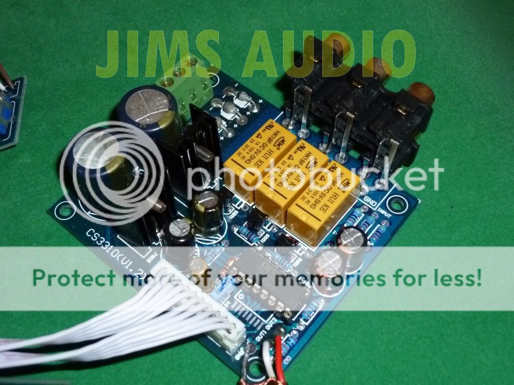
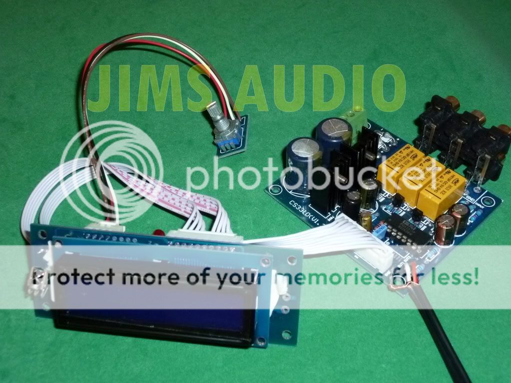
this is the kit that I got. no real docs so I had to ohm-out the board myself.
here's a key, hope its useful to someone other than myself:
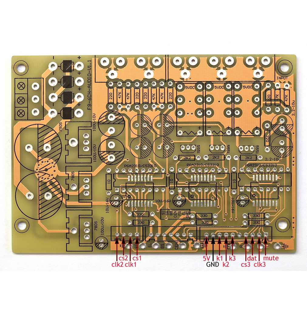
cs are chip-select lines. clk are clock lines.
note that 'dat' is common data line to all 3 chips.
k1-k3 are the relays for input selection (transistor driven).
vcc and gnd on the bottom row are for the 'remote processor' board (on the lcd). this is driven by the 3rd (lower left) 7805 regulator. if you don't need to power a remote controller cpu board then you only need the top 2 7805/7905 regulators for the analog rails. the digital 5v is 'derived' via 10ohms from the analog +rail.
inputs would be via rca jacks on the top and analog outputs are on the bottom row.
here's a key, hope its useful to someone other than myself:
cs are chip-select lines. clk are clock lines.
note that 'dat' is common data line to all 3 chips.
k1-k3 are the relays for input selection (transistor driven).
vcc and gnd on the bottom row are for the 'remote processor' board (on the lcd). this is driven by the 3rd (lower left) 7805 regulator. if you don't need to power a remote controller cpu board then you only need the top 2 7805/7905 regulators for the analog rails. the digital 5v is 'derived' via 10ohms from the analog +rail.
inputs would be via rca jacks on the top and analog outputs are on the bottom row.
Last edited:
Hi,
Thanks for posting that.
Your board looks like it'll do 5.1 ? I took the plunge on a 2 channel kit - I chose it because the kit comes with an A grade PGA chip and has an eeprom to remember settings. I'm most of the way through building it but am waiting on other things before I test it.
PGA2311 preamplifier remote volume control Rowland ! on eBay (end time 01-Mar-11 14:31:23 GMT)
No ground planes, the digital supply is shared with the analogue via 10r, both the analogue and digital share their gnd, and there's no decoupling near the chip either, so it isn't anywhere near what Ti suggest on their datasheet. Hey ho.
Thankfully it should be simple enough to hack the board and give an independent 5v for the mcu and another for the digital side of the PGA, and also easy enough to add local decoupling underneath.
On the plus side, all the caps were decent ( I only changed the post-reg caps to Panasonic FM 1000uF and the signal input coupling caps to BG NX HiQ with Vishay MKP bypasses), the regs are ON semi 7805 which, although 7805, are about as good as they get for noise, ripple rejection etc from a 7805, and the chip is A grade, so the kit is pretty good value for money. Such a shame about the board really.
One thing I can't fix are some of the pcb traces running near the PGA but I'm hoping this will only be a minor handicap and not appreciable in listening tests.
So it should be able to perform well enough despite the board's shortcomings.....I hope.
The seller was great - full marks to Stanton for his English and his willingness to to email me promptly, which I've needed as the instructions were little better than copying pictures.
One curious thing is the rectifiers - little grey and blue balls. Any idea who and where makes these and what their specs are ? Russian ?
Tom
Last edited:
I'm debating whether to do much to my board or not.
there is only a 10uf decouple cap and no provision for the usual .1's that people add (and the spec also suggests).
the 10 ohm R between A+ and D+ may not be so bad (one spec sheet does show that as an example) but I know from experience that this latch-up problem happens if you don't power on the analog and digital in the right sequence.
having the processor power supply on the same board is not such a great idea and neither are putting those diodes there. at the very least I think I'd remote the diodes offboard near the trafo. snubber them also while you are at it.
heck, even upgrade the psu from dual 7805 series to 317/337 series.
the chip will be only as good as the PSU feeding it. having a clean PSU matters.
the lack of care to ground is a concern and I'd only expect 'mid fi' from this board, though, to be honest. this is not even a semi-serious effort.
Thanks KlipshKid for finding this one
It is different from the other "red" and "blue" boards usually seen on ebay. Do you have the schema of this one ? Does it really remember last stetting ?
I am concerned about the low source impedance required by PGA2311 : from datasheet
It is different from the other "red" and "blue" boards usually seen on ebay. Do you have the schema of this one ? Does it really remember last stetting ?
I am concerned about the low source impedance required by PGA2311 : from datasheet
Output impedance is rarely mentioned in the specs of a source. I don't know how big a concern this should be. THD+N does not grow that much up to 2K but no info available beyond 2k.A source impedance of 600Ω or less is recommended. Source impedances up to 2kΩ will cause minimal degradation of THD+N.
BTW, KlipshKid, you could actually do a nice measurement if you have a very good souncard with two channel recording capabilities.
With free RMAA software you could measure your soundcard alone (direct out-direct in) and then measure again with the volume control board, at various attenuation levels.
RMAA enable to load up to 4 different measurements and compare them against each other. We would know the THD+N, IMD, crosstalk, etc. of this board.
Hi guys,
I can only agree with you Linuxworks. I'm not sure it's worth going to any great lengths - what's that saying about making a silk purse out of sow's ear ? I'm just going down the easy route of doing what I can to avoid the digital messing up the analogue.
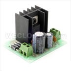
I can get 9V 6VA trans and 7805 regs etc pre-built here in HK for next to no money - US$15 for a pair of each - so it's easy and cheap enough to try using these for the digital power so it is independent from the analogue. I'm not expecting miracles.
GT*Mini Voltage Regulator (5V, 1A) - WECL Online
I've added snubbers to the weird-looking rectifiers (100pF iirc ) and some decoupling caps.
I think the schematic is the same as the one posted on the first page of this thread. I think the analogue is correct but the digital certainly isn't. I queried it and was told the schematic was for a previous version.
The memory works but you have to press a button on the remote to store the value - it doesn't automatically remember what it was when you turned it off. Better than nothing but...anyway, the eeprom is the 8 pin chip.
I might try the RMAA - never done that before. My PC has a pretty decent atx psu (Silverstone ST40NF) and an Onkyo SE200PCI soundcard that I replaced the op amps on with LME49720HA. I'd be interested to see what that's capable of anyway.
The problem is always time !
Tom
I can only agree with you Linuxworks. I'm not sure it's worth going to any great lengths - what's that saying about making a silk purse out of sow's ear ? I'm just going down the easy route of doing what I can to avoid the digital messing up the analogue.
I can get 9V 6VA trans and 7805 regs etc pre-built here in HK for next to no money - US$15 for a pair of each - so it's easy and cheap enough to try using these for the digital power so it is independent from the analogue. I'm not expecting miracles.
GT*Mini Voltage Regulator (5V, 1A) - WECL Online
I've added snubbers to the weird-looking rectifiers (100pF iirc ) and some decoupling caps.
An externally hosted image should be here but it was not working when we last tested it.
An externally hosted image should be here but it was not working when we last tested it.
An externally hosted image should be here but it was not working when we last tested it.
I think the schematic is the same as the one posted on the first page of this thread. I think the analogue is correct but the digital certainly isn't. I queried it and was told the schematic was for a previous version.
The memory works but you have to press a button on the remote to store the value - it doesn't automatically remember what it was when you turned it off. Better than nothing but...anyway, the eeprom is the 8 pin chip.
An externally hosted image should be here but it was not working when we last tested it.
I might try the RMAA - never done that before. My PC has a pretty decent atx psu (Silverstone ST40NF) and an Onkyo SE200PCI soundcard that I replaced the op amps on with LME49720HA. I'd be interested to see what that's capable of anyway.
The problem is always time !
Tom
Last edited:
all that I've read says you DO want to pre-buffer the pga chip.
drive it from a local low-z source if you can.
I like using discrete buffers when possible, such as these:
AMB Laboratories DIY Audio • View topic - Announce: new ?20 v2
they are small, extremely low noise and distortion and are unity gain stable (in fact, you don't want gain, the pga at 5v is not a high voltage device, exactly, on its inputs or outputs).
all that I've read says you DO want to pre-buffer the pga chip.
drive it from a local low-z source if you can.
Funny you say that, I was thinking it wouldn't make that much difference, but I live to be wrong. My DAC has a low-z output but the rest of my gear is the typical 100 ohm series and 47k shunt.
Tom
Hi guys
Did you see my touch-sense volume control?
http://www.diyaudio.com/forums/analog-line-level/183421-8-channel-touch-sense-remote-volume-controll.html
Yes, you do want a buffer to drive the PGAs.
w
Did you see my touch-sense volume control?
http://www.diyaudio.com/forums/analog-line-level/183421-8-channel-touch-sense-remote-volume-controll.html
Yes, you do want a buffer to drive the PGAs.
w
- Status
- This old topic is closed. If you want to reopen this topic, contact a moderator using the "Report Post" button.
- Home
- Source & Line
- Analog Line Level
- volume remote control module with PGA 2311