After a little research I've worked up a rough plan for a simple 10x2 mixer with 3 aux sends, the schematic bellow is just for a single channel strip, my plan is to use inverting virtual earth gain stages for each summing buss (master and auxes). Any input would be much appreciated (especially on the panning section). You can ignore the INA127 section. P1 is an insert return, K2 is for tape return, R14 and R15 feed the left and right mix buss respectively.
Attachments
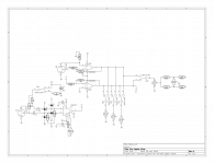
Should pins 2 and 3 of K2 be coupled through some caps for protection?.
P2 is an insert send to, p1 is the insert return, when nothing is inserted between the pre and aux section p2 and p1 are connected together. sw2-4 allow for the aux sends to be switched between the mic pre/channel path and the line in tape return (this mixer is designed for monitoring during the recording process).
What is the advantage to using the triple op-amp design from Rod Elliot:
http://sound.westhost.com/p30a_f4.gif
DC blocking and DC source
I found my op amp mixer (herald RA-88A) completely unable to cope with the DC offset of my quasi-sine wave generator, due to lack of blocking capacitors on inputs. Whereas my PAS2 preamp with 12AX7 tubes had no problem with it. Cost me a day of head scratching to find that DC bias on the home built source was the problem, not bad repair on the mixer. Most band mixers intentionally put DC on the inputs at the command of a switch, to power "phantom power" microphones. I find modern 5 or 10 uf 50V ceramic capacitors less worrisome than the traditional electrolytics in this location, although at $5 each they are a bit premium.
I found my op amp mixer (herald RA-88A) completely unable to cope with the DC offset of my quasi-sine wave generator, due to lack of blocking capacitors on inputs. Whereas my PAS2 preamp with 12AX7 tubes had no problem with it. Cost me a day of head scratching to find that DC bias on the home built source was the problem, not bad repair on the mixer. Most band mixers intentionally put DC on the inputs at the command of a switch, to power "phantom power" microphones. I find modern 5 or 10 uf 50V ceramic capacitors less worrisome than the traditional electrolytics in this location, although at $5 each they are a bit premium.
- Status
- This old topic is closed. If you want to reopen this topic, contact a moderator using the "Report Post" button.