I'm in the process of putting together a system with a Audio Sector Gainclone kit and a Pass Labs B1 input buffer. My main sources are a phono pre and a CD player. I will also have a mini jack input for my ipod or computer output for streaming audio such as Rhapsody or Pandora. Both my ipod and computer have a pretty low output. I want to be able to match the gain on that input to the level of the CD player which has nice output and the phono pre that has a gain control. I'd like to have all the levels equal before they go through the selector switch and then into the B1.
Is there a simple gain stage circuit with a pot that I can run the ipod/computer through to give it a little boost to match the rest of the sources?
Thanks, Scott
Is there a simple gain stage circuit with a pot that I can run the ipod/computer through to give it a little boost to match the rest of the sources?
Thanks, Scott
Easiest solution is a simple opamp gain stage... do you know how to configure one ?
http://users.ece.gatech.edu/mleach/ece3050/sp04/OpAmps01.pdf
http://users.ece.gatech.edu/mleach/ece3050/sp04/OpAmps01.pdf
Easiest solution is a simple opamp gain stage... do you know how to configure one ?
http://users.ece.gatech.edu/mleach/ece3050/sp04/OpAmps01.pdf
Thanks Mooly! I thought that might be it.
I have no idea how to configure one, I've just started learning about electronics and DIY audio. Any help would be greatly appreciated.
Scott
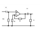
Here's the normal circuit...
The input impedance is set by Rin, so a normal value would be say 470k. That give a high input impedance that won't load any source you connect.
The gain is given by the formula Rf + R1 / R1.
So using standard values if RF were 22k and R1 were 10k the voltage gain is 3.2
What gain do you need... the only realistic way to find out is to use a pot for R1 and see. Then select a fixed resistor to fit in it's place (preset pots are horrible in audio circuits") )
)
The two caps... are good practice C1 certainly.
C2... I would say yes. The output of the opamp will be at zero volts DC... but again it's good practice to include it, however if the opamp is already feeding an AC coupled circuit then omit. The resistor R2 just defines the end of the cap to ground (100k).
Power supplies. You have to decide whether you want two single opamps or a dual.
The input impedance is set by Rin, so a normal value would be say 470k. That give a high input impedance that won't load any source you connect.
The gain is given by the formula Rf + R1 / R1.
So using standard values if RF were 22k and R1 were 10k the voltage gain is 3.2
What gain do you need... the only realistic way to find out is to use a pot for R1 and see. Then select a fixed resistor to fit in it's place (preset pots are horrible in audio circuits
)The two caps... are good practice C1 certainly.
C2... I would say yes. The output of the opamp will be at zero volts DC... but again it's good practice to include it, however if the opamp is already feeding an AC coupled circuit then omit. The resistor R2 just defines the end of the cap to ground (100k).
Power supplies. You have to decide whether you want two single opamps or a dual.
Attachments
Last edited:
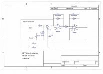
Another thought is to use the virtual earth configuration.
Have a look at this, which is the circuit I designed for my amp. Forget the FET's which are for electronic input selection.
R1 sets the input impedance. The gain of the opamp stage is just -R2/R1 (- because it inverts). The second stage inverts it back again.
This configuration is a "mixer" and each input has it's own R1 which allows each input to have it's level set to what is required. Different value of R1 for each input.
Attachments
Is that a single 18 volt rail ? In other words ground and +18 volts ?
If so, it's no problem...
Yes, just an 18 volt wall wart.
I'll redraw it for a single rail... now you can make this as simple or complex as you like, but for a single gain stage we'll keep it simple.
Thanks! simple is good for me at this point.
You need two "opamps" one for left one for right.
Opamps come in singles such as a TL071, duals, such as a TL072, or quads, such as a TL074.
I would suggest a dual, and on this forum wouldn't dare suggest any particular one
But you need something to use, and the TL072 is cheap, very good, and easy to work with. Use a socket and you can try others at will. Personally I prefer the OPA2604, but lets not go onto opamps and their merits.
Single supply, do you understand the first circuit here.
http://courses.cit.cornell.edu/ee476/ideas/singlesupply.pdf
Goto go... understanding that first circuit is key to understanding how the single rail biasing works. All you are really doing is providing a "false" ground... one that sits at half the supply.
Mention of opamps will bring hundreds of this or that is device is best...
I added my two penneth here from post #1017 lol,
http://www.diyaudio.com/forums/chip...g-audio-integrated-opamps-51.html#post2012422
Mention of opamps will bring hundreds of this or that is device is best...
I added my two penneth here from post #1017 lol,
http://www.diyaudio.com/forums/chip...g-audio-integrated-opamps-51.html#post2012422
You need two "opamps" one for left one for right.
Opamps come in singles such as a TL071, duals, such as a TL072, or quads, such as a TL074.
I would suggest a dual, and on this forum wouldn't dare suggest any particular one
But you need something to use, and the TL072 is cheap, very good, and easy to work with. Use a socket and you can try others at will. Personally I prefer the OPA2604, but lets not go onto opamps and their merits.
Single supply, do you understand the first circuit here.
http://courses.cit.cornell.edu/ee476/ideas/singlesupply.pdf
I can make sense of most of it.
After reading that I'm wondering, Would it be better to use a dual supply? I haven't purchased anything specific so It's not a problem.
Your gainclone will run on split supplies, so why not run the B1 buffer and opamp from the PSU there ? That to me is the best solution... neater, less possibility of ground loops etc.
If you don't want the preamp in the same box you can still run a "PSU out" from the gainclone to power low voltage stuff like preamps etc
Or did you want it all in separate boxes.
Have you bought the Pass buffer stuff/kit/bits etc ... because if matching all input levels is important, the opamp is the better solution used on it's own, feeding the gainclone directly.
Lot's of posibilities, up to you which route you want to go down
I will be building a similar circuit as well so maybe I join this discussion.
Input impedance is set by Rin, but can you explain why it is necessary to lower the impedance of the opamp circuit? Is it because audio source needs to have some load in order to perform well? I will be tapping between DSP and amplifier chip to add line out so I guess I don't need Rin resistor, right?
Input impedance is set by Rin, but can you explain why it is necessary to lower the impedance of the opamp circuit? Is it because audio source needs to have some load in order to perform well? I will be tapping between DSP and amplifier chip to add line out so I guess I don't need Rin resistor, right?
Your gainclone will run on split supplies, so why not run the B1 buffer and opamp from the PSU there ? That to me is the best solution... neater, less possibility of ground loops etc.
If you don't want the preamp in the same box you can still run a "PSU out" from the gainclone to power low voltage stuff like preamps etc
Or did you want it all in separate boxes.
Have you bought the Pass buffer stuff/kit/bits etc ... because if matching all input levels is important, the opamp is the better solution used on it's own, feeding the gainclone directly.
Lot's of posibilities, up to you which route you want to go down
My GC transformer is an Avel Y236652 250VA 25V+25V Toroidal
The B1 needs 18-24v single supply. Can that work together?
There is also the phono pre to consider DIY MM Phono Preamplifier Kit (Moving Magnet)
It looks like it needs a dual 12v supply.
I do have the B1 parts. I want to give this setup a try. I'll surely listen with and without it. I may decide to go without it.
I also don't know if the phono pre is going to have enough gain to match the rest of the sources. I thought there might be a mod to give it a bit more if needed.
Thanks Mooly for all your help. Greatly appreciated!
My GC transformer is an Avel Y236652 250VA 25V+25V Toroidal
The B1 needs 18-24v single supply. Can that work together?
Yes... a 25-0-25 vac transformer gives -/+ 35 volts DC after rectification.
You can use a simple zener shunt supply for this, it doesn't get any easier, just a resistor and zener to give a stable supply. The resistor is already there R1 in Nelsons circuit. The value would be calculated to give a few ma through the zener and to supply the circuit. The Zener connects across C1.
Typical value of R1 would be 35-24 (VCC- Zener) which is 11. That's the volt drop across the resistor. Value, what ? Nelson says it draws 20ma so allow 20 + 10 for the zener, that's 30ma. So R=V/I which is 11/0.030 which is 360ohms. Call it 390 common value. Wattage = (11*11)/390 which is 0.32 watts.
So a 1 watt would be chosen to ensure no problems with heat etc.
The Zener would be a 24 volt 1.3 watt again over rated. Even a half watt zener would be OK.
There is also the phono pre to consider DIY MM Phono Preamplifier Kit (Moving Magnet)
It looks like it needs a dual 12v supply.
Again that can all come from the main tranny, however 35 volts is the max input for 78 series regulators so it's a bit marginal to use them directly.
Choices again... you could use LM337 and 317 regs (these are adjustable regs but OK with up to 40 volts)... you also could use a similar zener supply to the above mentioned as opamps draw so little current.
You could make a simple "pre regulator" to drop the -/+35 volts to say -/+ 24 and then feed that to the 7812/7912.
http://www.datasheetcatalog.org/datasheet/nationalsemiconductor/DS009063.PDF
http://www.datasheetcatalog.org/datasheet/nationalsemiconductor/DS009067.PDF
On the phono preamp you can always alter the gain of the stages if needed, I'm sure it will be OK though.
Edit... the phono preamp in your link has a gain control anyway. And that's all you do, alter the value of the feedback resistor to alter the gain.
Last edited:
- Home
- Source & Line
- Analog Line Level
- Simple stereo gain stage