I will be building a similar circuit as well so maybe I join this discussion.
Input impedance is set by Rin, but can you explain why it is necessary to lower the impedance of the opamp circuit? Is it because audio source needs to have some load in order to perform well? I will be tapping between DSP and amplifier chip to add line out so I guess I don't need Rin resistor, right?
Do you need Rin ? depends on the circuit as a whole.
If you mean the non inverting amp, Rin also sets a DC voltage (ground) on the input pin which is essential if the device is AC coupled.
On the inverting stage it just sets input resistance whether AC or DC coupled.
A high Rin gives total compatability with all sources. Remember some old DIN spec stuff might have something like 10 or 100 k output impedance. Loading that with 10k just kills all the signal.
Perhaps if you start a thread and post a circuit with what you are trying to do
")
Great! thanks Mooly!
I'll digest the power supply situation. I'm trying to take enough time to understand what I'm doing here. I want to really learn as I go. You have been an incredible help so far!
OK, so I'll be using a dual power supply to power an OPA2604 [ in took a peak at some of the opamp discussions ] as you would.
Can you point me towards the simplest circuit to use?
I do want to use a pot. Would the pot take the place of R1 or would it just be an attenuator after the gain stage?
I'll digest the power supply situation. I'm trying to take enough time to understand what I'm doing here. I want to really learn as I go. You have been an incredible help so far!
OK, so I'll be using a dual power supply to power an OPA2604 [ in took a peak at some of the opamp discussions
] as you would.Can you point me towards the simplest circuit to use?
I do want to use a pot. Would the pot take the place of R1 or would it just be an attenuator after the gain stage?
Going back through the thread. I'm thinking the first circuit you posted is all I'll need.
What I don't understand is how the +/- voltage ties in.
The Gainclone uses a split supply.
The split supply means the output from the amp is normally zero volts (at ground potential) but can swing either positive or negative with respect to ground.
You have to understand that concept... the amp can push the speaker cone "out" by altering it's voltage closer to say the positive supply and pull the cone in by going toward the negative supply.
At all times the centre point or "zero" of the supply is our reference that all measurements are made from.
The opamps normally run on a similar split supply. The quiescent state is "zero" volts at the output, but they too can swing both positive and negative.
Nelsons B1 uses a single supply, ground and +24 volts. So keeping to our reference point (ground) the output can only ever go more positive (toward 24 volts). It can never deliver the "negative" part of the signal.
This is the bit you must understand,
So what we do is bias the output of the B1 (or an opamp that's using only single supplies) so that the output is sat at one half of the supply.
So again in Nelsons amp the output will be at +12 volts DC.
We MUST AC couple the amp using caps at the input and the output.
Any signal applied is now handled by the circuit, with the output swinging either higher than +12 volts or lower than plus 12 volts within the limits og the 24 volt supply.
To enable us to use that signal and couple it back to a DC coupled design like the gainclone means that steady bias of +12 volts has to be removed, that's what the output cap does on the B1.
So the simplest circuit to use... You must decide how you are going to power it.
1. Are you going to run it from the single supply to the B1.
2. Or arrange a split supply from the Gainclone.
3. Another option is to use the split supply of the phono preamp to power it.
Do you want the amp in one box ?????? in other words an integrated amp, or do you want everything in it's own box, all separates, each with it's own PSU.
Personally I would go for making an integrated, or at the very least powering all circuits from the one power amp. There's nothing worse than loads of PSU's and leads etc.
What I don't understand is how the +/- voltage ties in.
There are two pins for that which are left out in the circuit.
By the way, most often I see two opamps in a cascade. Is it because lower gain on each individual opamp is better than having higher gain on just one opamp?
Last edited:
There are two pins for that which are left out in the circuit.
By the way, most often I see two opamps in a cascade. Is it because lower gain on each individual opamp is better than having higher gain on just one opamp?
Sometimes, it depends on the circuit. At high gain the HF performance of the opamp deteriorates, so using more than one device is one option, cheaper and easier than designing a discrete solution or using a dedicated higher performance part, that might be less suitable in other areas.
I would thoroughly recommend a read at this,
The Audio Power Amplifier Design Handbook
The Audio Power Amplifier Design Handbook
Thanks for the incredible explanation!
I definitely want everything in one box. Gainclone, B1, phono, and ipod opamp gain circuit.
Can the one +25 -25 transformer handle all that without compromise?
It can easily handle it... you make sure there is no compromise by getting the grounding correct. And the rest of it
You have to have some idea how you are going to lay it all out... and it's vital that the main ground in the PSU is correct.
That means running a short wire from the connection between the two main reservoir caps to something (a bit of PCB etc) that you can make multiple connections too. That is the main ground reference.
I think you need to build it up one section at a time. Get the power amps working, initially with just a volume control at their input. Make sure they are OK and noise/hum free, then move on to the preamp stages.
Lay it all out on paper first, keep the transformer away from the input/preamp side of things physically.
One step at a time.
Hi,
Mooly has made a good job of guiding you through this basic electronics interconnection short course.
I would like to add, that you have two main choices when locating the various components.
1.) Integrated amplifier. This has the input sockets and Power Supply and pre-amp with gain and attenuator and Buffer and two Power Amps all inside one case. This requires that all your sources can drive the interconnect cables and the input of the integrated amplifier. The Buffer is not really required, it's an added extra that provides little if any benefit. However, if you decide to go with an inverting Power amplifier then a Buffer will ensure all the sources can drive the lowish impedance of the inverting inputs.
2.) Separate pre-amp and power amps.
The Power amp is just that. Input sockets, PSU and one or two amplifiers inside a case. And no attenuator, although switched gain settings can be an advantage.
The pre-amp has input sockets and PSU and pre-amp and attenuator and Buffer. This allows the preamp to be located beside the various sources or farther away. It also allows the power amp to be located close or much further away from the pre-amp.
This capability to locate all the major components some distance from each other is the main advantage of the pre+power combination.
I like my Power Amp right next to the speaker terminals
I like the Sources where it is convenient to operate/use them. Like the VCR is never under the TV.
I like the Attenuator close by the seating position.
How you want to operate the "system" determines which assembly route you take.
Last edited:
Thanks Andrew and Mooly! very helpful input, I'm amazed with the generous sharing of knowledge on this forum. Simply incredible!
This situation requires that everything be in the same enclosure, I could have separate PSU enclosure if needed. That may even be the best. Could I build up a PSU in a small enclosure with outputs for the different components? Would there be any benefit to that?
I've already got the amp kicking in a test assembly. Clean and quiet, It seems I got that part right. I also have a pair of 8" 2-ways built up in test boxes. I'm very happy with the sound of the two together but am still planning on experimenting on the GC. I want to build everything in test enclosures first to see how they all interact. So maybe the separate PSU test enclosure would be the right path. Or, since I'm not sure if I'll be sticking with the B1 or even the Phono pre { not sure how it will sound, it was a $25 kit} I should build all the circuits, Use wall warts as recommended to power the B1 and phono and get a recycled +12/-12 computer PSU for a couple bucks to power the opamp circuit? All for test purpose. Then I'd have everything I want to include working and I can make my decisions about how I want them to work together.
THAT'S IT! For now all test enclosures with test PSU's.
So, with that in mind. I want to make a opamp gain stage using a Opa2604 and a +12/-12 supply and also a pot. I don't need a lot of gain, I just want to match my ipod to the level of a CD payer.
Attachments
That's great you have the power amps working.
Another thought... any preamp stages, particularly any running on a single supply will cause switch on thumps and noises unless the volume is turned right down. It's always worth including a simple relay delay on the speaker outputs, maybe one also incorporating DC offset protection.
I wouldn't use a computer PSU. These are switch mode types... excellent at what they do... but not straightfoward for audio use. There's a lot of HF noise flying around and out of them.
If you want to try the OPA2604 I would power it from the GC PSU. The PSU is there and waiting to be used... you can always power it differently later... just build the stage first and see what you think.
Do you make your own PCB's or use Veroboard etc ?
Suppose you want an OPA2604 circuit now... with pot
Point to point is possible... but it's not ideal as you have to support the thing.
Prototyping board (it's many many years since I last used that stuff) is probably better.
Up to you...
Do you want a circuit to use for the OPA2604 then ?
If you use a socket at first you can try different opamps and see if you prefer one over another.
Prototyping board (it's many many years since I last used that stuff) is probably better.
Up to you...
Do you want a circuit to use for the OPA2604 then ?
If you use a socket at first you can try different opamps and see if you prefer one over another.
You might find this of use,
http://focus.ti.com/lit/an/sboa092a/sboa092a.pdf
http://focus.ti.com/lit/an/sboa092a/sboa092a.pdf
Point to point is possible... but it's not ideal as you have to support the thing.
Prototyping board (it's many many years since I last used that stuff) is probably better.
Up to you...
Do you want a circuit to use for the OPA2604 then ?
If you use a socket at first you can try different opamps and see if you prefer one over another.
Yes, One to use the OPA2604 would be great! Thanks, Scott
I will try the socket.
Something like this then,
First grab a copy of the data sheet for the 2604 which I have posted at the bottom.
Any opamps you order, make sure you get the DIP (not surface mount) version which is the OPA2604AP.
Circuit is straightfoward.
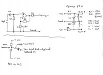
PSU first... the opamps takes so little current that a simple PSU is all that is required.
So the input to the PSU consists of three connections that go to the main PSU in the GC.
Do you see how the star earth is a small offshoot from the connection between the main caps. That's because large currents (100/120hz) flow as the caps are continually charged.
Taking the ground away from there eliminates this.
Don't underestimate that issue... it's a very real problem. Always use the offshoot to a make a "clean" ground point.
The opamp PSU is a simple zener stabilised supply. ZD1 and 2 can be anywhere from 12 to 18 volts for most opamps, giving a -/+ 24 to 36 volt split supply.
The opamp has two power pins, pin 8 is positive, pin 4 is negative. The rails don't have to be exactly equal... it wouldn't matter if one were +12 and the other -20.
The caps C1 and C2 are small decouplers, value not critical. You can usefully add a 0.1uf polystyrene cap directly across each zener to cut noise if you want.
The opamp... look at the data sheet... see the two amps and the pinouts within the package.
Cin... I would choose around 0.47uf poly cap and use a value of 470k for Rin. Rin sets the input impedance. If it's lower, Cin needs to be larger to prevent loss of low frequencies as Cin and Rin form a high pass filter.
If you really want the theory behind one resistor and one cap,
RC circuit - Wikipedia, the free encyclopedia
Rf and the pot. I have kept the pot in the "earthy" end of the circuit to minimize stray pickup (using a pot isn't ideal... you are much better initially using one, then fitting fixed resistors... but up to you)
Values... Rf 22k and 10k or 22k for the pot.
R2 is to ensure total stability if driving capacitive load (cable)... it normally isn't needed.
If you fit it use 68 ohm and fit as close to the IC as possible.
Why no output cap... because it's a FET opamp and the offset will be very low.
First grab a copy of the data sheet for the 2604 which I have posted at the bottom.
Any opamps you order, make sure you get the DIP (not surface mount) version which is the OPA2604AP.
Circuit is straightfoward.
PSU first... the opamps takes so little current that a simple PSU is all that is required.
So the input to the PSU consists of three connections that go to the main PSU in the GC.
Do you see how the star earth is a small offshoot from the connection between the main caps. That's because large currents (100/120hz) flow as the caps are continually charged.
Taking the ground away from there eliminates this.
Don't underestimate that issue... it's a very real problem. Always use the offshoot to a make a "clean" ground point.
The opamp PSU is a simple zener stabilised supply. ZD1 and 2 can be anywhere from 12 to 18 volts for most opamps, giving a -/+ 24 to 36 volt split supply.
The opamp has two power pins, pin 8 is positive, pin 4 is negative. The rails don't have to be exactly equal... it wouldn't matter if one were +12 and the other -20.
The caps C1 and C2 are small decouplers, value not critical. You can usefully add a 0.1uf polystyrene cap directly across each zener to cut noise if you want.
The opamp... look at the data sheet... see the two amps and the pinouts within the package.
Cin... I would choose around 0.47uf poly cap and use a value of 470k for Rin. Rin sets the input impedance. If it's lower, Cin needs to be larger to prevent loss of low frequencies as Cin and Rin form a high pass filter.
If you really want the theory behind one resistor and one cap,
RC circuit - Wikipedia, the free encyclopedia
Rf and the pot. I have kept the pot in the "earthy" end of the circuit to minimize stray pickup (using a pot isn't ideal... you are much better initially using one, then fitting fixed resistors... but up to you
)Values... Rf 22k and 10k or 22k for the pot.
R2 is to ensure total stability if driving capacitive load (cable)... it normally isn't needed.
If you fit it use 68 ohm and fit as close to the IC as possible.
Why no output cap... because it's a FET opamp and the offset will be very low.
Attachments
Absolutely............Do you see how the star earth is a small offshoot from the connection between the main caps. That's because large currents (100/120hz) flow as the caps are continually charged.
Taking the ground away from there eliminates this.
Don't underestimate that issue... it's a very real problem. Always use the offshoot to a make a "clean" ground point.
It seems like I have been preaching this for years and still I see builders proposing otherwise and advisors still telling beginners to locate the main Audio star Ground between the smoothing caps. AAgh.
Follow Mooly's advice to the letter. It is the same as Leach and Self and JLH and many other experts.
Absolutely.
It seems like I have been preaching this for years and still I see builders proposing otherwise and advisors still telling beginners to locate the main Audio star Ground between the smoothing caps. AAgh.
Follow Mooly's advice to the letter. It is the same as Leach and Self and JLH and many other experts.
Hi Andrew,
Yes, I remember years ago being puzzled about how the "hum" changed as you moved the connections "along" that centre wire between the caps.
Surely if you put it in the "middle" it must be right.
As you say Arghhhh
- Home
- Source & Line
- Analog Line Level
- Simple stereo gain stage