Dear All,
First off I should say I am not a pro in Electronics. Second I should say I am not a great believer in "Special source" Hifi.
Why do I not just use Op-amps?
Partly for the fun of it. Partly because people are always swapping them out to get "better" sound.
I have a pair of Quad ESL 63 and am trying to design an active cross over. I have a CX3400 which I used to make my LINN HELIX speakers active, but cross over frequencies for 2 way active filtering don't cross over low enough for my ESL 63 so its time for better.
I have read the following articles.
At the moment I am wondering:
Parts should be available from a standard supplier like Farnell and not supper expensive which limits the value of C3,4,5,7,8 to a Capacitance:100nF; Capacitance Tolerance:± 1%. £1.22 Where as 68nF ± 1% are 49pence.
I will probably build 4 of the above so I can do AB Stereo comparisons and will experiment with cross over frequencies between 100-300 Hz.
For Now I will use my old Linn speakers as the sub woofer.
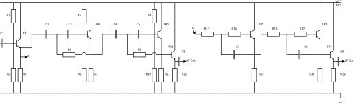
Here is a circuit I am starting with, feed back would be appreciated.
First off I should say I am not a pro in Electronics. Second I should say I am not a great believer in "Special source" Hifi.
Why do I not just use Op-amps?
Partly for the fun of it. Partly because people are always swapping them out to get "better" sound.
I have a pair of Quad ESL 63 and am trying to design an active cross over. I have a CX3400 which I used to make my LINN HELIX speakers active, but cross over frequencies for 2 way active filtering don't cross over low enough for my ESL 63 so its time for better.
I have read the following articles.
- tube active crossover.htm
- Active 3-Way Crossover for Loud Speaker Systems
- Elliott Sound Products Linkwitz-Riley filter
- 4 way crossover with signal detect
- 3-way active XO
- ACTIVE CROSSOVER
- Synergy active crossover
- crossover pcbs
At the moment I am wondering:
- what resistors I should use for biasing TR2 and TR3. I assume these will effect the cross over network.
- If I need TR4 and TR7 output buffers.
- If 12 V gives enough headroom considering 4 transistors will have 0.6 Base Emitter drop for biasing.
Parts should be available from a standard supplier like Farnell and not supper expensive which limits the value of C3,4,5,7,8 to a Capacitance:100nF; Capacitance Tolerance:± 1%. £1.22 Where as 68nF ± 1% are 49pence.
I will probably build 4 of the above so I can do AB Stereo comparisons and will experiment with cross over frequencies between 100-300 Hz.
For Now I will use my old Linn speakers as the sub woofer.
Here is a circuit I am starting with, feed back would be appreciated.
Attachments
Looks OK, but you are missing the caps for R14 and R17. The value of R5 and R6, and R9 and R10 should be double what your crossover calculator tells you.
I was working on a project very much like this, I may be able to do some boards or at least a layout for you.
I was working on a project very much like this, I may be able to do some boards or at least a layout for you.
Last edited:
Thanks for the encouragement richie00boy. And the values for R5 and R6, and R9 and R10. Could you please clarify
Also I found this thread, active filter without opamps with the link to Naxo active crossovers by Linn/NIAM.
As I was thinking C7 and C* would be the capacitors for the filter.but you are missing the caps for R14 and R17.
Thats great news as we might help each other.I was working on a project very much like this, I may be able to do some boards or at least a layout for you.
Also I found this thread, active filter without opamps with the link to Naxo active crossovers by Linn/NIAM.
For the low-pass filter, the bias network needs to form your R2, so the value you get for R2 with whatever formula you are using, double that value should be used for both the resistors in the bias network as the capacitor sees them in parallel.
For the high-pass filter you are missing the corresponding capacitors for R14 and R17.
For the high-pass filter you are missing the corresponding capacitors for R14 and R17.
I decided to use the formulars from ESP Linkwitz-Riley Electronic Crossover which are
Since I don't have windows and like python I wrote a simple calculator, which I attached and some sample output. This leads me to select, the following information
So 68nF it is as I expect the cross over to be around 100-150Hz for the final version. As it keeps R not too much higher at 15K than the 10K used by ESP circuit and the 11K used by the Active 3-Way Crossover
Code:
(1)   R = 1 / (2 * π * 1.414 * f * C)
(2)   C = 1 / (2 * π * 1.414 * f * R)
(3)   f = 1 / (2 * π * 1.414 * R * C)
Code:
C=0.000000068000
f=352 R=4700
f=295 R=5600
f=243 R=6800
f=220 R=7500
f=201 R=8200
f=165 R=10000
f=150 R=11000
f=137 R=12000
f=110 R=15000
f=91 R=18000
f=82 R=20000
f=75 R=22000
f=68 R=24000
f=61 R=27000
-
So 68nF it is as I expect the cross over to be around 100-150Hz for the final version. As it keeps R not too much higher at 15K than the 10K used by ESP circuit and the 11K used by the Active 3-Way Crossover
Ops I forgot to attach the output in
Attached here unfortunately as a zip file to include the python and output text.Since I don't have windows and like python I wrote a simple calculator, which I attached and some sample output.
Attachments
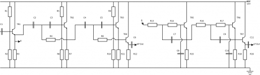
I looked at it more than 10 times then realized your right I am missing
Thank you so much for your help richie00boy")
Attached is a revised schematic. I updated the capacitor numbers due to the two additional capacitors added for R14 and R17.the corresponding capacitors for R14 and R17.
Thank you so much for your help richie00boy
Attachments
Please correct me if I am wrong. A lot of this is guess work on my part and not because I am an expert.
For the high pass
For the low pass
I have no opinions on Transistor choice, so some help would be nice.
Since for the Transistor TR7, R19 voltage will be slightly more than 2.1 Volts lower than the voltage between at the base of TR1, I may have to up the voltage of supply for now I will leave it as it still leaves me some headroom, I wonder how I can calculate this.
For now I will assume, BC337. I have no knowledge as to where their maximum linearity is, but I do know, Max current is 800 mA, and 10mA is the maximum frequency response, so I assume probably wrongly 10mA would be a good standard current to have running through these transistors. Looking at Designing Bipolar Transistor Audio PreAmplifiers suggests 5mA but being a little on the higher side will allow me to save calculating to many values for when its lower.
Assuming they all have the same transistors, and Voltage is set so approximately half VCC they should be set so the transistors are in the center of their linear operation. Keeping with my target of 12V supply. 6V will be set across all of
This would lead to the value of approximately, 600 Ohms for all these resistors.
For the input buffer I will assume for now,
Giving an input Bias of TR1 of 7.2 Volts, which leaves only 4.3 Volts before definite clipping, maybe I need to increase the supply voltage?
So the questions I have assuming all is correct are.
Costs look like 10-15 Euros for filter capacitors, 4 Euros for transistors and another 5 Euros for resistors and output capacitors.
Again all feed back is welcome.
For the high pass
Code:
C2,C3,C4,C5 = C
R4,R5,R6,R8,R9,R10=2R
Code:
R13, R14, R16, R17 = R
C8, C9 = C
C7, C9 = 2CSince for the Transistor TR7, R19 voltage will be slightly more than 2.1 Volts lower than the voltage between at the base of TR1, I may have to up the voltage of supply for now I will leave it as it still leaves me some headroom, I wonder how I can calculate this.
For now I will assume, BC337. I have no knowledge as to where their maximum linearity is, but I do know, Max current is 800 mA, and 10mA is the maximum frequency response, so I assume probably wrongly 10mA would be a good standard current to have running through these transistors. Looking at Designing Bipolar Transistor Audio PreAmplifiers suggests 5mA but being a little on the higher side will allow me to save calculating to many values for when its lower.
Assuming they all have the same transistors, and Voltage is set so approximately half VCC they should be set so the transistors are in the center of their linear operation. Keeping with my target of 12V supply. 6V will be set across all of
Code:
R3,R7,R11,R12,R15,R18,R19For the input buffer I will assume for now,
Code:
R1 = 160K
R2 = 240K
Giving an input Bias of TR1 of 7.2 Volts, which leaves only 4.3 Volts before definite clipping, maybe I need to increase the supply voltage?
So the questions I have assuming all is correct are.
- Is the BC337 a good choice of transistor, if not how should I pick one?
- Is 4.3 Volts head room enough? If not how much would help?
- Should I put a volume control between TR3/TR4 and TR6/TR7?
- If no volume control do I need TR4/TR7?
- Current in transistors.
- Building some thing this simple will have good or better sound than an Op amp solution.
Costs look like 10-15 Euros for filter capacitors, 4 Euros for transistors and another 5 Euros for resistors and output capacitors.
Again all feed back is welcome.
BC337 are ok as are BC549C, which is what I usually use. I would use a higher supply than 12V, 24V ones are easy to come by. The voltage won't much affect the design anyway.
High-pass and low-pass 4th-order boards shown, no output buffers (yet). I have included a JFET load instead of resistor so you might want to get some 2N3819 and 510 ohm resistors. Just make sure you buy 5mm pitch caps, I use the polyester box types.
I also have a discrete pre-amp which I would put before these boards to buffer the source and provide volume adjustment.
I'll look at your post in detail another time.
High-pass and low-pass 4th-order boards shown, no output buffers (yet). I have included a JFET load instead of resistor so you might want to get some 2N3819 and 510 ohm resistors. Just make sure you buy 5mm pitch caps, I use the polyester box types.
An externally hosted image should be here but it was not working when we last tested it.
I also have a discrete pre-amp which I would put before these boards to buffer the source and provide volume adjustment.
I'll look at your post in detail another time.
Last edited:
I had a quick look at the BC549C suggested and the fact it instantly give hits with Google for low noise and specifies noise specifications makes me think that the BC549C is a good choice. I also feel the suggestion to move to 24 V is a good idea for head room reasons.
I will update my circuit calculations soon. I am still looking forward to the end result.
Thanks again richie00boy.
I will update my circuit calculations soon. I am still looking forward to the end result.
Thanks again richie00boy.
Thank you Andrew for the suggestion. The BC550 is less plentiful in Farnel's catalog so instantly ruled out.
Not that I know much about reading data sheets I have tried to compare the BC560C and the BC549C. With my understanding their is little to call between them, 0.5 dB in noise advantage to the advantage of BC549C and 10V advantage to the BC560C. Since I am only planning around 24V with a single ended supply, I think the differences are minimal in this case?
Not that I know much about reading data sheets I have tried to compare the BC560C and the BC549C. With my understanding their is little to call between them, 0.5 dB in noise advantage to the advantage of BC549C and 10V advantage to the BC560C. Since I am only planning around 24V with a single ended supply, I think the differences are minimal in this case?
After looking at the data sheet of the BC549C assuming a 24 V supply so expecting approximately 12 V across the transistor, with a 10 mA standing current (As that's again the collector current with maximum gain) I looked at the power dissipation on the transistor. At 120 mW dissipation in the transistor with the transistor spec sheet it says 1.5 W maximum dissipation (the BC560 has 500 mW Max), this is a factor of 10 inside the maximum dissipation. Since the transistor spec sheet had 12 mW/C temperature coefficient, this would make the transistor raise its temperature my 10 C. This seems a little hot to my mind.
Looking at the gain curve with collector current, I noticed that gain is essentially flat from 5mA to 25mA so it seems safe to half the current to 5 mA which ties in with Designing Bipolar Transistor Audio PreAmplifiers.
So this brings me to the new value of 2.2 K for
Any last feed back before I create make an order with farnell. I will post the order codes for each item here before I place the order too.
Looking at the gain curve with collector current, I noticed that gain is essentially flat from 5mA to 25mA so it seems safe to half the current to 5 mA which ties in with Designing Bipolar Transistor Audio PreAmplifiers.
So this brings me to the new value of 2.2 K for
Code:
R3,R7,R11,R12,R15,R18,R19Hi Owen, You might also want to have a look at the B1 Active Crossover thread It was the thread that inspired me to come up with the synergy active crossover, but unlike the synergy it is a fully discrete design, NO opamps A number of people have built variations of jacques' design and reported good results. If you are planning on making multiple crossovers and comparing I think it would be one you should have on your list.
I personally decided to go with the opamps as I wanted to do something not sallen key, and I don't have enough knowledge to design a discrete circuit to do what the GIC blocks (using opamps) can do. Unfortunately I still haven't built it yet. The speaker project has been taking precedence. But it will hopefully be largely finished (the speakers) after this coming weekend.
You could also consider doing something that uses opamps, but instead use one of the "discrete" opamps (ie built from discrete components but behaves like an opamp) such as Nelson Pass describes in this article something I will have to read myself because it could be a stepping stone for a fully discrete synergy active crossover.
Good luck and keep us informed of your results!
Tony.
A number of people have built variations of jacques' design and reported good results. If you are planning on making multiple crossovers and comparing I think it would be one you should have on your list. I personally decided to go with the opamps as I wanted to do something not sallen key, and I don't have enough knowledge to design a discrete circuit to do what the GIC blocks (using opamps) can do. Unfortunately I still haven't built it yet. The speaker project has been taking precedence. But it will hopefully be largely finished (the speakers) after this coming weekend.
You could also consider doing something that uses opamps, but instead use one of the "discrete" opamps (ie built from discrete components but behaves like an opamp) such as Nelson Pass describes in this article something I will have to read myself because it could be a stepping stone for a fully discrete synergy active crossover.
Good luck and keep us informed of your results!
Tony.
Last edited:
the spec has two dissipation values. The Tc is held at 25degC and Ta is held at 25degC these are not the same.
Use Ta value and de-rate to actual operating ambient temperature. Inside a case this could be 25degC to 50degC.
Then decide what proportion of the maximum de-rated dissipation you want to use.
Some go as high as 50%, others as low as 10%.
If your de-rated dissipation is 400mW then 120mW is 30%. Many would consider this figure acceptable.
However, this will result in a slow change in transistor parameters as the system warms up to the final Tj when reached.
At the output end where parameters tend to be less important I would consider 30% OK.
At the front end I believe parameters can influence the amplifier's performance more and I would tend towards 10%.
Dear Tony,
Your quite right the b1-active-crossover.html should have been referenced.
At work I go for smoking breaks and some times over lap with an analogue chip designer, which I did today, I showed him the circuit. he suggested to minimize distortion I might benefit by using Op Amps in the filter stages as their gain will closer approximate 1 as well as removing DC offset issues, or alternatively use darlingtons to increate the gain and then pay attention to the bias values. He is probably correct. If this design does not sound good (my measurement kit is only an ebay oscilloscope and a pair of ears).
May years ago I built a "shunt feedback" op-amp RIAA pickup amplifier and was amazed how good it sounds. I am not adverse to using op-amps because of this experience. Since moving to Germany I don't have my record players and more importantly my records. Because of this my computer feeds a DAC which is chip based so my system is not 100% discrete anyway.
I hope you get your speakers finished soon, and I am sorry to hear you haven't finished your cross overs yet. Good luck with all this.
Thank you for the feedback.
Owen
Dear Andrew,
Thank you for addressing the issue that is most bothering me most about this design, the decision of how to bias the transistors. I guess I will stick on the low side of the standing current as I would rather the circuit does not drift too much during operation. 5mA makes for 15% and is still in the maximum gain area which should minimize the distortion my smoking break colleague was concerned with.
I will post an updated schematic with the volume controls added in the output buffer very soon.
Thanks for clarifying design decisions I had not thought of, such as warm up.
Owen
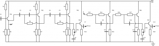
Here is the updated schematic, I have added a variable resistor and a capacitor for the output buffers.
Due to not using a new biasing network on the output buffer I save an additional capacitor between TR3/TR4 and TR6/TR7 this may not be a good idea if the transistors hfE is not high as the base current may lead to excessive voltage drop across VR1/2 this is especially true for TR7.
TR7's emitter may be in the worse case which may be 5V-6V lower than the voltage at the base of TR1. Seems a 24V supply is definitely needed, and maybe more care over DC offset.
Regards
Owen
Attachments
How come you need level controls on the crossover - do your amps not have them?
It's worth having a play with a discrete design, the only thing I would say is that you must make sure your power supply is very clean and stable, as the circuit is a lot more susceptible to that than an op-amp one would be.
It's worth having a play with a discrete design, the only thing I would say is that you must make sure your power supply is very clean and stable, as the circuit is a lot more susceptible to that than an op-amp one would be.
- Status
- This old topic is closed. If you want to reopen this topic, contact a moderator using the "Report Post" button.
- Home
- Source & Line
- Analog Line Level
- Active Crossover Using transistors.