I'm thinking some XLR cables have three conductors (for pins 1, 2, and 3) and a shield (effectively four conductors between each end), and the XLR ring in the schematic connects to the shield of the cable. The 100k puts the shield 'approximately' at ground without creating a possible ground loop from however things are connected at the other end, and the small cap makes the shield a "hard ground" at RF frequencies. That may not be exact, but I'd think it's something like that.
This classic webpage (Rane Technical Note 110: Sound System Interconnection) may also help explain things if the bewildering options don't add to the mystery:
Sound System Interconnection
Is there a manual for the unit from Peavey? That might have a short explanation. Otherwise, if you don't get a satisfactory answer in this thread, you might ask Jensen or Rane about it.
I poked around, this looks like your thread over on Peavey here:
• View topic - Peavey ID-4? (What is it?)
Here's the "single" version, the ID1G:
http://www.peavey.com/assets/literature/manuals/1d1g.pdf
This one has a ground lift switch, presumably just like the Jensen schematic. I'm wondering why the 4-channel version doesn't have ground lift switches.
And yeah, that pin 1 connection you show in post#20 looks strange. Are you sure that transformer connection is to one end of a coil? I wonder if it's actually a shield.
Last edited:
Yup, thats my thread. And there's virtually no info on the web about it. It appears that you may be right about the transformer case. That pin doesn't seem to connect to either coil end, but it does short to the case. I didn't want to initially meter the transformer because it says not to in a tech paper on the Jensen site.
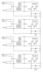
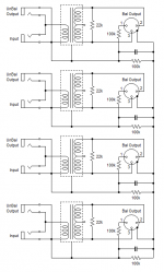
Now I'll have to mod that drawing one 'mo time.
Edit: Here's the "new" schematic. Pretty sure its correct this time.
My meter does confirm that there's 400k between any two pin 1's, 100k between input jack grounds and pin 1 or XLR barrel, and 200k between pin 1 and XLR barrel.
Now I'll have to mod that drawing one 'mo time.
Edit: Here's the "new" schematic. Pretty sure its correct this time.
My meter does confirm that there's 400k between any two pin 1's, 100k between input jack grounds and pin 1 or XLR barrel, and 200k between pin 1 and XLR barrel.
Attachments
Last edited:
- Status
- This old topic is closed. If you want to reopen this topic, contact a moderator using the "Report Post" button.