OK I've redone the sim and have values for the resistors. I also changed the synergy to have the 220K output resistors and 100K input resistors on the DCB1 buffer stages to better represent the load of your buffers. It didn't make that much difference.
I think that these values should provide a transfer function within approx 0.2db of your existing one.
Note that the resistor numbers in the sim don't match the resistor numbers on the shcematic and BOM I posted earlier, though they are in the same positions.
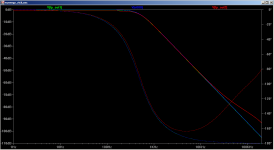
attached is output sim and the schematic fragment.
red trace is the synergy output. Please ignore the lower level before the corner freq, this is something odd with the sims. It does a perfect (no loss) transfer function in the real implementation, matching sims I did in PCD exactly.
R22 4.87K and R26 2.32K in the sim schematic are the two values you will need to get to best match your current transfer function with the RLC network.
R22=R4 and R26=R12 in the schematic I posted in post #205
On the question on recommendations of values for q of 0.7 I think we are good, but what I would really like to see is gated measurements of your drivers (under specific guidelines) so I could sim the actual effect of the electrical filters on the drivers themselves.
Tony.
I think that these values should provide a transfer function within approx 0.2db of your existing one.
Note that the resistor numbers in the sim don't match the resistor numbers on the shcematic and BOM I posted earlier, though they are in the same positions.
attached is output sim and the schematic fragment.
red trace is the synergy output. Please ignore the lower level before the corner freq, this is something odd with the sims. It does a perfect (no loss) transfer function in the real implementation, matching sims I did in PCD exactly.
R22 4.87K and R26 2.32K in the sim schematic are the two values you will need to get to best match your current transfer function with the RLC network.
R22=R4 and R26=R12 in the schematic I posted in post #205
On the question on recommendations of values for q of 0.7 I think we are good, but what I would really like to see is gated measurements of your drivers (under specific guidelines) so I could sim the actual effect of the electrical filters on the drivers themselves.
Tony.
Attachments
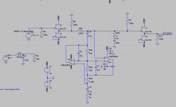
Hi Andrew see post 217 first image for the lp_out1 VN008 is between R2 and C4 on the passive circuit on the left side. That passive circuit is what the active part is emulating... and that passive circuit is in turn a different realisation of Ricks RLC which is between a couple of buffers in post 217.
Tony.
Tony.
Last edited:
Rick, to be perfectly honest, I have a hard time following your filter approach. One of the main attractions of active filtering is the avoidance of coils, which are costly and mostly a nuisance.
Now you are putting it all upside down in using coils/inductances.
What is the expected advantage of your venture? Furthermore what is wrong in your opinion with either a classic S&K active filter @ 450Hz or Tony s approach with a gyrato i.e. an active emulation of a coil/inductance?
Eelco
Now you are putting it all upside down in using coils/inductances.
What is the expected advantage of your venture? Furthermore what is wrong in your opinion with either a classic S&K active filter @ 450Hz or Tony s approach with a gyrato i.e. an active emulation of a coil/inductance?
Eelco
No gate stoppers? Just making sure. Just noticed this.
I would make any measurement I can.
Just tell me how to do it.
My power supplies are slightly under +- 15 volts - cannot imagine that being a problem. Let me know if you think it might be.
Finally got my other channel working with the buffered LC crossover. Using a pair of PA Sjostrom's "SUPER BUFFERS" (diamond buffer) as the first buffer and my existing FET buffers as the output. Will be able to build some more FET buffers this weekend and substitute for the SUPER BUFFER. (just got the parts I needed)
The SUPER BUFFER sounds just fine. No warts at all. I assume the FET ones will sound better but will know for sure in a few days.
Figured those SUPER BUFFERs would blast right through the LC. The heatsinks on the JUNG Super Regulators are warm now with the SUPER BUFFER installed.
I have some good 2SK170s on the way for the SYNERGY board.
Now with both sub500 hz horns using the semi-passive filter (instead of filters at the woofer) the promise of what I heard with just one was not a broken one. It is amazing how much better this sounds than the choke and cap after the amplifier. And for Boden's benefit than an SK opamp filter.
Tonight this same channel gets the peaking high pass crossover. Had to wait for the choke to be liberated to do it.
Might be a long night of listening.
Hi Rick I just removed them for the sim. The real circuit has them check the schematic in post 205 ") I'm using 220 ohms, but your not using that part anyway so I took them out in the sim. I don't think they make any difference to the transfer function but I can add them back in to check. They are mostly there for stability.
I'm using 220 ohms, but your not using that part anyway so I took them out in the sim. I don't think they make any difference to the transfer function but I can add them back in to check. They are mostly there for stability.
Still working but will give you the run down later this weekend
Tony.
I'm using 220 ohms, but your not using that part anyway so I took them out in the sim. I don't think they make any difference to the transfer function but I can add them back in to check. They are mostly there for stability. Still working but will give you the run down later this weekend
Tony.
Hi Rick, I normally use holmimpulse for doing the measurements not sure if you use it or not.
But I'm going to need a bit more info. I assume these are three ways?
My setup is an MTM with passive crossover with a 10" woofer in a separate enclosure which acts as the stand.
I did my measurements half way between the woofer and the MTM at a distance of about 66CM (outside) That was about the best I could get as I was crossing a bit lower and needed decent measurements down to around 200Hz at least.
The important thing is not to move the mic between measurements.
I measured the MTM with it's crossover (ie the crossover between M's and T) reason being that it has BSC in it and some corrections and without that it would be difficult simulating it's interaction with the woofer.
I locked time zero in Holm
I measured the woofer
I then measured both the woofer and the MTM running together.
The third measurement allows you to work out the Z offset.. https://www.google.com.au/url?sa=t&...pS9NMoPog&sig2=DNHSkc0ncNw6cSHYxojvAw&cad=rja horizontal and vertical you can measure with a tape measure.
I'm pretty sure I then took measurements on axis with the MTM's tweeter and with the centre of the woofer for the final use in the PCD sim (I'll have to check back and see if I documented it).
It may also be useful to have a nearfield measurement of the woofer for blending in if you can't get a good gated response to low enough (I had to).
So depending on your setup the measurement setup might be a bit different. The important bit though is to get the measurement with both running so that the z offset can be worked out.
With these measurements it's then possible to simulate what the effect of the filters will be in Passive Crossover Designer (and optimize the slopes to get a good accoustic rollof and phase matching, this is I think the best part about using the synergy, it makes implementing non-standard tranfer functions easy, provided it can be done with an LC or LCL filter) . For a sanity check you can load in a flat line response and apply the filter to that and then compare it to the actual measured response of the crossover. That's what I did with my synergy to make sure it was really behaving like the sims predicted it should.
Hope that wasn't too much of a ramble!!
Tony.
Tried to use HOLM but it refused to install on my WIN10 machine.
I think I can do something similar with REW but did not try.
Got my 170/74 fets and wanted to replace the Sjostrum buffers but I could not get them to work. Either they are fakes or I am doing the same thing wrong over and over.
So no testing was done this weekend.
Hoping to get things working tonight.
I haven't tried Holm on Windows10... Will need to try installing it on my Daughters laptop.
The most important thing is to make sure that the time zero does not change between measurements. I'm not sure how to do that in REW (maybe it is the default).
Bummer about the buffers, hope it turns out to be a simple problem, maybe getting another set of eyes (not necessarily mine! ) on it might help.
Tony.
The most important thing is to make sure that the time zero does not change between measurements. I'm not sure how to do that in REW (maybe it is the default).
Bummer about the buffers, hope it turns out to be a simple problem, maybe getting another set of eyes (not necessarily mine!
) on it might help. Tony.
I figure I had to have got something WRONG for my FETs.
Got four sets and none of them do anything but sound like Bill Wyman's fuzz box.
Ordered some more from a fellow in California. Hope these are real.
The circuit is so simple it would be almost impossible to do it wrong. Other than applying the wrong power polarity which I did with one of the first pair I got from the DIYAudio store.
In limbo until they arrive.
Maybe do a simple IDSS test on them. I assume they are BL grade. Should have IDSS between about 6 and 11 mA from memory.
I accidentally hooked up my proto synergy board with wrong polarity. The only thing that blew were the electros.. the J170's were unaffected luckily.
Are these additional boards you have done (ie already have some working ones)? I'm wondering whether you have an oscillation.....
Tony.
I accidentally hooked up my proto synergy board with wrong polarity. The only thing that blew were the electros.. the J170's were unaffected luckily.
Are these additional boards you have done (ie already have some working ones)? I'm wondering whether you have an oscillation.....
Tony.
For my penance I must make a public confession for my FET problem.
I was not connecting signal ground and power supply ground.
Why I would think I did not need to do that is beyond me. AS soon as I connected them they worked just fine. Terribly embarrassing. Wrote the fellow in Honk Kong a letter of apology for accusing him of selling defective devices. I made no formal complaint, thankfully. His devices are just fine and matched for those, like me, who have not bothered to find out how. Plus I do not want to buy that many bulk devices. (typical excuse?)
So now I can go back to speaker and crossover work.
Must say the LC filter sounds incredible. If the SYNERGY sounds better than this I will be very happy. The whole crossover scheme is working well and I know I have even begun to really tweak it.
Yes, I should have sent you a picture!
Take care,
- Status
- This old topic is closed. If you want to reopen this topic, contact a moderator using the "Report Post" button.
- Home
- Source & Line
- Analog Line Level
- The Synergy "Active" Crossover