Hi James, at the moment the physical realization of the circuit (for initial sanity check) has no volume pot and has 22K resistors to ground off the input directly before the gates of the jfet.
The second pot on the high pass is supposed to be there to allow me to adjust the levels on the highpass circuit as my woofers are not as efficient as the MTM's (I don't think) I guess I will find out if it is necessary when I actually hook it up to some speakers")
I guess I could implement the volume control on the output rather than the input followed by another buffer. I originally had some extra buffers in the circuit but have stripped it back a lot. I'll try that in the sim and see how it goes.
No probs to change the input pot to 7.5k in the sim, I'll set up a new file with the requested mods and see how it goes Might not get to it today but should be soon.
I'm also going to have a look at different configs of the GIC for the FDNR, this was the config that seemed to work ok in the sim, but some of the other configs are theoretically better.
Once I have a finalized circuit you are more than welcome to design a pcb for it at this stage I suspect I will do something on verro board, but a good pcb would be nice!
edit: good point on the gate stoppers, I took them out at some point in the sim and it didn't seem to cause a problem (I originally had 220R ones). I should put them back in and see if that effects the anomalies around 58K and 75K.
Tony.
The second pot on the high pass is supposed to be there to allow me to adjust the levels on the highpass circuit as my woofers are not as efficient as the MTM's (I don't think) I guess I will find out if it is necessary when I actually hook it up to some speakers
I guess I could implement the volume control on the output rather than the input followed by another buffer. I originally had some extra buffers in the circuit but have stripped it back a lot. I'll try that in the sim and see how it goes.
No probs to change the input pot to 7.5k in the sim, I'll set up a new file with the requested mods and see how it goes
Might not get to it today but should be soon. I'm also going to have a look at different configs of the GIC for the FDNR, this was the config that seemed to work ok in the sim, but some of the other configs are theoretically better.
Once I have a finalized circuit you are more than welcome to design a pcb for it
at this stage I suspect I will do something on verro board, but a good pcb would be nice! edit: good point on the gate stoppers, I took them out at some point in the sim and it didn't seem to cause a problem (I originally had 220R ones). I should put them back in and see if that effects the anomalies around 58K and 75K.
Tony.
Last edited:
I do agree with George (Lightspeed Vol Control) about the benefits of avoiding standard pots and trimmers and IMHO there is less signal quality loss by having the vol adjust on low pass filters and if you need some gain there, change the output buffer to a simple 2sk170 gain stage like Juma's or even add the possibility of turning it into a Link transform bass boost cct (adjustable) and run your MTMs as B2 alignment (sealed box)
About a pcb, might be worth looking at doing the FDNRs as plug in modules and keep all the jfets, filter caps, etc together
Salas has got the recent simple LV Shunt regs working well - might as well go for quality supplies altho John Brown (EC Design) has done a rather good version of the isolating dual Cmultiplier that is very quiet indeed and a rather surprising natural sound - both so far better than any of the enhanced 3 pin regulators that I've tried - plenty options ...
One other thing that comes to mind - on the SIM, you have a couple of 1000kR resistors - ie 1Meg R - not sure about this, but in there a point where quality suffers, or noise starts to become a problem, at these levels w/out higher voltages applied?
Maybe someone well versed in this will add some expert facts to these vague ideas ...
Hi James,
I ran the sim a few times tonight. At high frequency (14Khz) the mod improves, at low freq (the 200Hz crossover freq) it is the other way around (though the differences are tiny in that case). I'll have to check at a few other frequencies. Note that the mod was getting rid of the 12K resistors, putting in a 22ohm gate stopper and dropping the volume pot to 7K
here are the results of the sims.
original circuit 14Khz
DC component:1.34029e-005
Harmonic Frequency Fourier Normalized Phase Normalized
Number [Hz] Component Component [degree] Phase [deg]
1 1.400e+04 2.083e-04 1.000e+00 -127.58° 0.00°
2 2.800e+04 5.894e-10 2.830e-06 96.39° 223.96°
3 4.200e+04 3.626e-11 1.741e-07 -158.56° -30.99°
4 5.600e+04 5.956e-12 2.860e-08 -106.53° 21.04°
5 7.000e+04 5.572e-11 2.675e-07 -4.38° 123.19°
6 8.400e+04 6.891e-12 3.309e-08 169.33° 296.90°
7 9.800e+04 8.851e-11 4.250e-07 -63.70° 63.88°
8 1.120e+05 3.847e-12 1.847e-08 85.43° 213.00°
9 1.260e+05 5.565e-11 2.672e-07 -117.34° 10.24°
Total Harmonic Distortion: 0.000289%
Fourier components of V(hp_out)
DC component:-1.28941e-005
Harmonic Frequency Fourier Normalized Phase Normalized
Number [Hz] Component Component [degree] Phase [deg]
1 1.400e+04 9.293e-01 1.000e+00 1.56° 0.00°
2 2.800e+04 1.190e-05 1.281e-05 156.59° 155.03°
3 4.200e+04 2.257e-07 2.429e-07 40.33° 38.77°
4 5.600e+04 2.587e-08 2.784e-08 53.89° 52.34°
5 7.000e+04 1.846e-07 1.986e-07 -160.58° -162.14°
6 8.400e+04 1.770e-08 1.905e-08 -34.39° -35.95°
7 9.800e+04 1.733e-07 1.865e-07 95.34° 93.78°
8 1.120e+05 1.408e-08 1.516e-08 -134.26° -135.82°
9 1.260e+05 1.631e-07 1.756e-07 0.80° -0.76°
Total Harmonic Distortion: 0.001282%
Date: Sat Feb 04 18:17:31 2012
with JH's requested mods 14Khz
Fourier components of V(lp_out)
DC component:1.31347e-005
Harmonic Frequency Fourier Normalized Phase Normalized
Number [Hz] Component Component [degree] Phase [deg]
1 1.400e+04 2.293e-04 1.000e+00 -121.31° 0.00°
2 2.800e+04 2.358e-10 1.028e-06 79.78° 201.09°
3 4.200e+04 6.561e-11 2.861e-07 -146.70° -25.39°
4 5.600e+04 1.458e-11 6.358e-08 -29.43° 91.88°
5 7.000e+04 3.336e-11 1.455e-07 11.96° 133.27°
6 8.400e+04 1.860e-11 8.112e-08 -33.53° 87.78°
7 9.800e+04 8.842e-11 3.856e-07 -47.77° 73.54°
8 1.120e+05 1.718e-11 7.491e-08 -60.09° 61.22°
9 1.260e+05 8.167e-11 3.561e-07 -94.92° 26.39°
Total Harmonic Distortion: 0.000120%
Fourier components of V(hp_out)
DC component:-1.32832e-005
Harmonic Frequency Fourier Normalized Phase Normalized
Number [Hz] Component Component [degree] Phase [deg]
1 1.400e+04 9.774e-01 1.000e+00 1.59° 0.00°
2 2.800e+04 6.091e-06 6.232e-06 119.32° 117.73°
3 4.200e+04 2.252e-07 2.305e-07 1.56° -0.03°
4 5.600e+04 2.409e-08 2.465e-08 -77.32° -78.91°
5 7.000e+04 1.791e-07 1.833e-07 -132.89° -134.48°
6 8.400e+04 1.887e-08 1.931e-08 -176.48° -178.07°
7 9.800e+04 1.642e-07 1.680e-07 132.19° 130.61°
8 1.120e+05 1.815e-08 1.857e-08 86.19° 84.60°
9 1.260e+05 1.577e-07 1.614e-07 42.54° 40.95°
Total Harmonic Distortion: 0.000624%
Date: Sat Feb 04 17:11:12 2012
200Hz original circuit
Fourier components of V(lp_out)
DC component:1.30535e-005
Harmonic Frequency Fourier Normalized Phase Normalized
Number [Hz] Component Component [degree] Phase [deg]
1 2.000e+02 4.741e-01 1.000e+00 -88.61° 0.00°
2 4.000e+02 1.163e-06 2.452e-06 -85.78° 2.83°
3 6.000e+02 8.195e-10 1.729e-09 16.51° 105.12°
4 8.000e+02 1.298e-10 2.737e-10 89.81° 178.42°
5 1.000e+03 7.122e-11 1.502e-10 -58.26° 30.34°
6 1.200e+03 4.154e-11 8.762e-11 -42.61° 45.99°
7 1.400e+03 6.361e-11 1.342e-10 -168.93° -80.33°
8 1.600e+03 9.054e-11 1.910e-10 -46.23° 42.38°
9 1.800e+03 8.559e-11 1.805e-10 140.21° 228.82°
Total Harmonic Distortion: 0.000245%
Fourier components of V(hp_out)
DC component:-1.11205e-005
Harmonic Frequency Fourier Normalized Phase Normalized
Number [Hz] Component Component [degree] Phase [deg]
1 2.000e+02 4.666e-01 1.000e+00 90.15° 0.00°
2 4.000e+02 1.386e-06 2.969e-06 141.54° 51.39°
3 6.000e+02 4.378e-09 9.383e-09 83.84° -6.32°
4 8.000e+02 1.308e-10 2.804e-10 -32.04° -122.19°
5 1.000e+03 8.828e-11 1.892e-10 -134.40° -224.56°
6 1.200e+03 9.096e-11 1.949e-10 178.11° 87.96°
7 1.400e+03 7.045e-11 1.510e-10 156.96° 66.81°
8 1.600e+03 7.097e-11 1.521e-10 129.91° 39.76°
9 1.800e+03 7.101e-11 1.522e-10 158.79° 68.63°
Total Harmonic Distortion: 0.000297%
Date: Sat Feb 04 20:01:38 2012
200Hz JH mod
Fourier components of V(lp_out)
DC component:1.25898e-005
Harmonic Frequency Fourier Normalized Phase Normalized
Number [Hz] Component Component [degree] Phase [deg]
1 2.000e+02 4.936e-01 1.000e+00 -88.59° 0.00°
2 4.000e+02 1.274e-06 2.581e-06 -86.26° 2.33°
3 6.000e+02 6.700e-10 1.357e-09 28.94° 117.53°
4 8.000e+02 5.111e-11 1.036e-10 -31.10° 57.49°
5 1.000e+03 5.226e-11 1.059e-10 -167.13° -78.53°
6 1.200e+03 7.521e-11 1.524e-10 75.96° 164.55°
7 1.400e+03 8.942e-12 1.812e-11 158.55° 247.15°
8 1.600e+03 2.944e-11 5.964e-11 -35.13° 53.47°
9 1.800e+03 6.306e-11 1.278e-10 -47.92° 40.67°
Total Harmonic Distortion: 0.000258%
Fourier components of V(hp_out)
DC component:-1.11842e-005
Harmonic Frequency Fourier Normalized Phase Normalized
Number [Hz] Component Component [degree] Phase [deg]
1 2.000e+02 4.908e-01 1.000e+00 90.15° 0.00°
2 4.000e+02 1.538e-06 3.133e-06 137.63° 47.47°
3 6.000e+02 3.530e-09 7.193e-09 51.00° -39.16°
4 8.000e+02 1.720e-10 3.504e-10 -29.62° -119.78°
5 1.000e+03 7.109e-11 1.448e-10 -158.01° -248.17°
6 1.200e+03 2.130e-11 4.340e-11 127.54° 37.38°
7 1.400e+03 3.013e-11 6.139e-11 -91.06° -181.21°
8 1.600e+03 9.854e-11 2.008e-10 -157.28° -247.44°
9 1.800e+03 1.140e-10 2.323e-10 135.33° 45.18°
Total Harmonic Distortion: 0.000313%
Date: Sat Feb 04 21:04:14 2012
edit: I used the 1 meg resistors on output as that is what salas used on the output of the DCB1 I think nelson used 220K. the higher the resistance the higher the current noise, but I'm not sure if that is applicable in shunt or only in series. I guess if I get hiss I can try changing them to something lower
Tony.
Last edited:
Well I decided to hook up the single channel to the amps today and see what I get. LOTS of noise! Probably not surprising considering my dodgy breadboard layout with no thought put into grounding at all
I could also hear what appeared to be the effects of some oscillation on the woofers, sort of a high pitched noise that started lowish and increased in freq before dropping back down and starting again.
I listened to some music despite the problems and it sounded pretty good. The midrange seemed clearer, and seemed vocals seemed to loose a small amount of reverb (which sounds better).
Levels when playing low and high off separate channels of the same amp are not too bad, perhaps even a little bass heavy (but that may just be that I've got used to it being bass shy).
The real problem is when I use the chipamp for highs and the playmaster for lows. The chipamp has too much gain (I think it is 32X) I'd lower it if it were easy but unfortunately it is not, since my p2p job pretty much makes that impossible without a complete rebuild
I hooked up the scope and I had a nice oscillation at about 370Khz at about 350mV Peak to peak with the 22K resistors in the FDNR. That is probably contributing to the noise problem!! using the 40K resistors has dropped that down to about 200mV peak to peak.
I'm unsure whether this is simply a layout issue or something inherently wrong with the circuit. I will try and work out what the problem is. If the worst comes to the worst, the high pass works fine and I will drop back to a boring old sallen key on the bass. But I would like to get it working
I've been looking for a simple inverting low gain discreet amp to use after the low pass. I don't like having to wire the bass speakers up reversed in polarity. I guess it is just psychological though as if I invert the signal instead I guess it is the same final result It looks like some head scratching and testing for a while...
Tony.
I could also hear what appeared to be the effects of some oscillation on the woofers, sort of a high pitched noise that started lowish and increased in freq before dropping back down and starting again.
I listened to some music despite the problems and it sounded pretty good. The midrange seemed clearer, and seemed vocals seemed to loose a small amount of reverb (which sounds better).
Levels when playing low and high off separate channels of the same amp are not too bad, perhaps even a little bass heavy (but that may just be that I've got used to it being bass shy).
The real problem is when I use the chipamp for highs and the playmaster for lows. The chipamp has too much gain (I think it is 32X) I'd lower it if it were easy but unfortunately it is not, since my p2p job pretty much makes that impossible without a complete rebuild
I hooked up the scope and I had a nice oscillation at about 370Khz at about 350mV Peak to peak with the 22K resistors in the FDNR. That is probably contributing to the noise problem!! using the 40K resistors has dropped that down to about 200mV peak to peak.
I'm unsure whether this is simply a layout issue or something inherently wrong with the circuit. I will try and work out what the problem is. If the worst comes to the worst, the high pass works fine and I will drop back to a boring old sallen key on the bass. But I would like to get it working
I've been looking for a simple inverting low gain discreet amp to use after the low pass. I don't like having to wire the bass speakers up reversed in polarity. I guess it is just psychological though as if I invert the signal instead I guess it is the same final result
It looks like some head scratching and testing for a while... Tony.
two mods done with no success.
1. I changed the bypass caps on the pins of the 2604 to 15nf instead of 100nf, no change.
2. added 220 ohm gate stoppers on the input. no change.
I suspect that the problem is driving the capacitive load that the FDNR cricuit presents.
The worst point is on pin one of the opamp, which is effectively driving a 100nf cap, at that point the oscillation is ~400mV p2p. I may need to follow some of the recommendations in the datasheet for driving capacitive loads.
Unfortunately due to the very low frequency of the crossover (relative to the frequencies normally used with FDNR's) I need a "big" cap in order to keep the resistor values low enough. If I decrease the caps to 10nf, I need to increase the resistors 10 fold, the most problematic being the 15.8K one which is in series with the signal. I may have to try with a 158K resistor here though in the end
Tony.
There's a whole different sound going on between the ol' Playmaster and that Chipamp, particularly with the MTM speaker configuration - suggest you do a quick check to see what phase differences there are about 100, 200 and 400Hz just on the amp's outputs (load resistors for 1 ch each amp and CRO the 2 signals - nothing elaborate, indication only)
So, high pass filter is behaving itself quite well and sound okay from 200Hz upwards, and changing the gate stoppers didn't show any problems, same with input pots so that's a good couple of potential difficulties out of the way
So, the low pass 'filter' is the problem and changing the 2 X 22kR resistors (R18, 20) up to 44kR just about halved the amplitude but didn't change the freq of oscillation so that's not the source - I take it that either the C4, C5 or C6 are the offending caps - perhaps just add another 0.1 in // to each in turn to see if the osc freq changes
- can you physically fit another gate stopper in front of J11? [as you can see, great believer in gate stoppers - easy way to trim the sound of the stage]
One step at a time - later on it might be a good idea to knock up a pcb to check out the difference in sound using the ol' proven SK low pass filter and we probably need to look at some phase correction and gain stages anyway.
Incidently, I think that using a simple jfet gain stage (for the low pass inefficiency) like a BOZ cct, inverts the signal.
Don't worry about same voltage supply for the ICS - be different supplies in actual use, so just use what's best for quality ....
Thanks Allen and Al I've redone the FDNR GIC swapped the location of the upper cap and lower resistor. With the 40K values it had a massive resonant peak around 30Khz, I tried simming a few times and 608R looked good but didn't work well in reality. Just put in 1K and no oscillation (yay). The measurement in holm doesn't look great but it's a start The most surprising thing is that it had zero effect on the distortion in the sim, the THD amount was identical at 0.000247 at 200Hz.
I had intended to try the 2134 instead of the 2604 at some point but it is a bit of a pain to swap it out due to the way I've done the breadboarding, but I will give it a try
Tony.
I've redone the FDNR GIC swapped the location of the upper cap and lower resistor. With the 40K values it had a massive resonant peak around 30Khz, I tried simming a few times and 608R looked good but didn't work well in reality. Just put in 1K and no oscillation (yay). The measurement in holm doesn't look great but it's a start The most surprising thing is that it had zero effect on the distortion in the sim, the THD amount was identical at 0.000247 at 200Hz. I had intended to try the 2134 instead of the 2604 at some point but it is a bit of a pain to swap it out due to the way I've done the breadboarding, but I will give it a try
Tony.
Attachments
Last edited:
hmm seems I spoke too soon. With shorted input I still have oscillation. Now at about 110Khz, about 200mV p2p that probably explains the noise in the impulse response. It also seems that the value of the resistors sets the ocillation frequency.
with 680R the osc is at 130Khz, with 1K it is at 116Khz and with 1.3K it is at 110Khz, 40K was around the 30Khz mark. Not sure what the deal is yet but maybe if I sleep on it I'll have an idea
Tony.
that probably explains the noise in the impulse response. It also seems that the value of the resistors sets the ocillation frequency. with 680R the osc is at 130Khz, with 1K it is at 116Khz and with 1.3K it is at 110Khz, 40K was around the 30Khz mark. Not sure what the deal is yet but maybe if I sleep on it I'll have an idea
Tony.
Hi Jay, that's a very good question and something I had not considered! I'm going to need to think about that and probably do some measurements. I did reverse the phase on the speaker connection to the woofers, but that's not what you are concerned about is it. More that the passive crossover is going to introduce additional delay, that we will need to add into the LP section.
Tony.
Tony.
Just an update, I've been experimenting with dfferent configurations of the fdnr, have something better but it still has some issues. I'm going to try Al's suggestion of using the opa2134 instead of the 2604. I just did a sim and it looks like it has much less of a phase issue, and actually with the new configuation seems to give a better result than the opa2604 did before. Hopefully that will solve the issue.
I'll get to your question later Jay once I have the circuit sorted
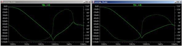
sim just finished and thd went from 0.000247 to 0.000248 it seems that the opamp in use is making very little difference (which is kinda the design goal). second pic right is 134.
Tony.
I'll get to your question later Jay once I have the circuit sorted
sim just finished and thd went from 0.000247 to 0.000248
it seems that the opamp in use is making very little difference (which is kinda the design goal). second pic right is 134. Tony.
Attachments
The 2134 wasn't a magic bullet. At first it seemed worse but playing around with the compensation caps I got something of an improvement. Note this doesn't have the 25 ohm resistors that are in the circuit diagram above.
I tried various values for the compensation cap (based on what I had in the junk draw). 37pf gave the best result. I'm thinking I'll buy a couple of trimmer caps tomorrow. 8.5 - 100pf. It might work yet!!
Tony.
I tried various values for the compensation cap (based on what I had in the junk draw). 37pf gave the best result. I'm thinking I'll buy a couple of trimmer caps tomorrow. 8.5 - 100pf. It might work yet!!
Tony.
Attachments
The situation has improved!
The addition of the trimmer cap seems to have mostly fixed the oscilation issue. Ironically whatever the default value of the trimmer cap is seems to be pretty close to the value that fixes the issue. I have not adjusted them at all, just put them in circuit.
I hooked it up to the amp as well and the extremely high level of noise is gone. There is some noise but I suspect it is about the same as when the HT PC is connected directly to the amp. I should probably verify this with the scope.
subjectively (listening to one channel only) There is a lot more bass (not surprising since the -3db on the 10" boxes is around 34Hz and it is around 90 Hz on the MTM's) and the mids now sound cleaner (also to be expected since they aren't trying to reproduce frequencies they stuggle with).
I've not done anything to try and work out the mid /bass levels as yet, I'll do some pink noise measurements at the listening position, but probably in reality I need to have both channels done before I can do that.
I'm suspicious that there may be distortion in the low pass circuit but it is based on listening to just the bass (ie 12db /oct LR at 200Hz) through the MTM's it sounded distorted, but it could just be because I was only hearing a fraction of what I normally would. It sounds fine when playing with both the woofers and the MTM's
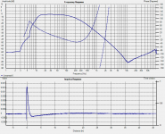
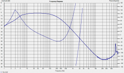
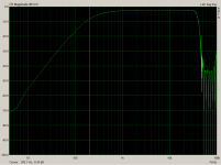
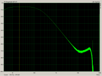
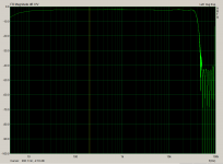
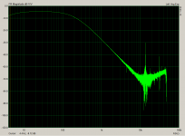
pic shows the measurement I did last night. Only at 96Khz sampling rate because I realised that the 75Khz spike on the 192Khz measurements is inherent to the on board sound card, so I have gone back to the trusty old Audigy II ZS.
looking at the FR in real time in arta shows some issues still, tuning the trimmers hopefully will address this.
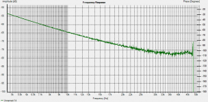
1st pic shows the current result, and the second is a zoom showing that there are some problems after about 5Khz, I suspect still some residual oscillation. you can also see that the slope starts to lessen at about 10Khz but I'm not too concerned about this.
Tony.
The addition of the trimmer cap seems to have mostly fixed the oscilation issue. Ironically whatever the default value of the trimmer cap is seems to be pretty close to the value that fixes the issue. I have not adjusted them at all, just put them in circuit.
I hooked it up to the amp as well and the extremely high level of noise is gone. There is some noise but I suspect it is about the same as when the HT PC is connected directly to the amp. I should probably verify this with the scope.
subjectively (listening to one channel only) There is a lot more bass (not surprising since the -3db on the 10" boxes is around 34Hz and it is around 90 Hz on the MTM's) and the mids now sound cleaner (also to be expected since they aren't trying to reproduce frequencies they stuggle with).
I've not done anything to try and work out the mid /bass levels as yet, I'll do some pink noise measurements at the listening position, but probably in reality I need to have both channels done before I can do that.
I'm suspicious that there may be distortion in the low pass circuit but it is based on listening to just the bass (ie 12db /oct LR at 200Hz) through the MTM's it sounded distorted, but it could just be because I was only hearing a fraction of what I normally would. It sounds fine when playing with both the woofers and the MTM's
pic shows the measurement I did last night. Only at 96Khz sampling rate because I realised that the 75Khz spike on the 192Khz measurements is inherent to the on board sound card, so I have gone back to the trusty old Audigy II ZS.
looking at the FR in real time in arta shows some issues still, tuning the trimmers hopefully will address this.
1st pic shows the current result, and the second is a zoom showing that there are some problems after about 5Khz, I suspect still some residual oscillation. you can also see that the slope starts to lessen at about 10Khz but I'm not too concerned about this.
Tony.
Attachments
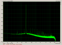
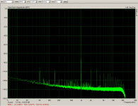
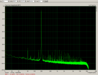
I have today been trying to tune out the remaining noise at high frequencies in the low pass crossover. All I found was that there was a fairly large range where the noise was minimum, and jumped up dramatically either end of that range, but that removing it completely didn't work.
I suspect this is due to the distance I have the caps from where they need to be due to limitations of the bread board. So I really need to do a proper layout and build it properly before I will find out the true situation.
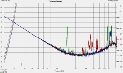
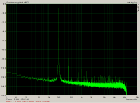
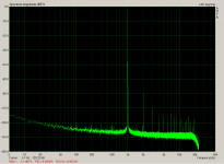
However that being said I did a few more measurements anyway. At first I was getting shocking thd at low frequencies until I realised that I needed to drop the sampling rate down from 192Khz to 48Khz after that the low frequency figures were much more reasonable (went from around 1%thd to about 0.002%)
anyway attached are some pics. I'll have to baseline the sound card in loop back as well for comparison. The 50 Hz is the usual I get with anything on this PC, and will be affecting the figures somewhat.
I feel happier about going to the trouble of doing a proper layout after doing these measurements though
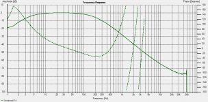
I think most of the images should be self explanatory, the last three are the sound card in loopback with nothing changed from what was used for the other measurements. 3rd and 4th are lowpass, 5th and 6th are highpass.
Tony.
I suspect this is due to the distance I have the caps from where they need to be due to limitations of the bread board. So I really need to do a proper layout and build it properly before I will find out the true situation.
However that being said I did a few more measurements anyway. At first I was getting shocking thd at low frequencies until I realised that I needed to drop the sampling rate down from 192Khz to 48Khz
after that the low frequency figures were much more reasonable (went from around 1%thd to about 0.002%) anyway attached are some pics. I'll have to baseline the sound card in loop back as well for comparison. The 50 Hz is the usual I get with anything on this PC, and will be affecting the figures somewhat.
I feel happier about going to the trouble of doing a proper layout after doing these measurements though
I think most of the images should be self explanatory, the last three are the sound card in loopback with nothing changed from what was used for the other measurements. 3rd and 4th are lowpass, 5th and 6th are highpass.
Tony.
Attachments
-
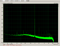 highpass_1k_thd.png26.4 KB · Views: 52
 -
 highpass_200Hz_thd.png23.2 KB · Views: 51
 -
 lowpass_1khz_thd.png26.2 KB · Views: 58
 -
 lowpass_200hz_thd.png26.4 KB · Views: 57
 -
 highpass_fr.png17.9 KB · Views: 62
 -
 synergy_lowpass.png18.4 KB · Views: 75
 -
 soundcard_loopback.png16.6 KB · Views: 54
 -
 soundcard_loopback_200Hz.png23 KB · Views: 53
 -
 soundcard_loopback_1khz_thd.png22.8 KB · Views: 51
I just tried the 2604 again in the updated circuit with the trimmer caps. It is a lot more sensitive, and I could not get rid of the high frequency issues. I guess once I make a proper board I can try it, but it looks like I should get myself a couple more 2134's.
The attached was the absolute best I could tune the trimmers, only a very small movement iether way resulted in substantially more hash above 10K. Whether it is layout or the circuit I guess I may find out once I make the proper prototype.
Tony.
The attached was the absolute best I could tune the trimmers, only a very small movement iether way resulted in substantially more hash above 10K. Whether it is layout or the circuit I guess I may find out once I make the proper prototype.
Tony.
Attachments
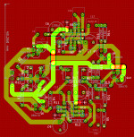
It's been a long time coming but I recently started to work on a layout for the Synergy. I'll post up what I have so far as I think it is good enough now for prototype status
I've since last posting also found that I can make the circuit behave as a third order filter by the addition of one resistor in the low pass, or one capacitor in the high pass, which is great for flexibility. The layout of course allows for this.
I also recently had the idea that since the filter simulates a passive crossover I could use speaker workshop with actual driver measurements to optimize the filter elements to get a desired acoustic slope. It's pretty simple to do. Just make a dummy impedance with all vales set to 1 ohm for the low pass, or the value of the load resistor for the highpass, then simulate away!
This seems to hold promise! The measurements I had were pretty roller coaster like (taken at the listening position) so I 1 ocatve smoothed them... possibly not the best approach. I may try getting some decent outside measurements to use instead.
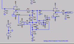
The attached schematic has junk values in it for the filter section, just whatever I had been experimenting in spice, but I've attached in case anyone is interested to see the latest incarnation. Layout is double sided (I intend to use a chinese board house to get some prototypes).
I'll probably end up using an lme49860 or the LM4562 chip, as it simulates much better in the low pass than the opa2134 and gets lower distortion in the high pass. One interesting thing though is that it needs quite different values for the "damping" resistors. Quite a bit lower values.
Anyway attached is the layout and schematic it was made from (I used kicad). I'll have to stop obsessing about it and send it off to get some boards made!
Tony.
I've since last posting also found that I can make the circuit behave as a third order filter by the addition of one resistor in the low pass, or one capacitor in the high pass, which is great for flexibility. The layout of course allows for this.
I also recently had the idea that since the filter simulates a passive crossover I could use speaker workshop with actual driver measurements to optimize the filter elements to get a desired acoustic slope. It's pretty simple to do. Just make a dummy impedance with all vales set to 1 ohm for the low pass, or the value of the load resistor for the highpass, then simulate away!
This seems to hold promise! The measurements I had were pretty roller coaster like (taken at the listening position) so I 1 ocatve smoothed them... possibly not the best approach. I may try getting some decent outside measurements to use instead.
The attached schematic has junk values in it for the filter section, just whatever I had been experimenting in spice, but I've attached in case anyone is interested to see the latest incarnation. Layout is double sided (I intend to use a chinese board house to get some prototypes).
I'll probably end up using an lme49860 or the LM4562 chip, as it simulates much better in the low pass than the opa2134 and gets lower distortion in the high pass. One interesting thing though is that it needs quite different values for the "damping" resistors. Quite a bit lower values.
Anyway attached is the layout and schematic it was made from (I used kicad). I'll have to stop obsessing about it and send it off to get some boards made!
Tony.
Attachments
Tony,
Did you ever have a listen to this particular filter design?
I built the original Acheron version but the filter components are quite a bit off the right values and I couldn't ever get a satisfactory result and gave it away as a project - I ended up with a reasonable version of the Sallen Key filter with the DCB1 buffers - it's okay, but not top line - loss of definition, dynamics, etc - might go back to using valve buffers but not so sure about the sound of the SY gyrator filter.
Hi James, I did briefly, but only one channel as that was all I had the wires for on the breadboard. I didn't run it too long because of the ocilation issues, which were causing quite a bit of noise.
However even with that going on there was a definite improvement running with the synergy compared to just listening to my MTM. This is two fold, one thing was that I had deeper bass extention due to the 10" vifa, and the second was cleaner sound from the MTM as it was now only doing from 200Hz up.
That was a straight textbook 2nd order LR filter on both low and highpass. What I have since realised is that it is relatively easy to get what will give a proper acoustic slope, by simulating the passive version and then implenting the same filter with the synergy. The sim I did, using 3rd oder on the low pass and 2nd order on the high pass I got a very good match to an acoustic 4th order bessel. This is what I intend to implement.
SY has an error in his calculations on his website. I don't believe he has corrected it yet He's been seduced by digital crossovers and I think the Acheron has fallen by the wayside. I did find that in simulation the gyrator (as used in Sy's Acheron) had quite high distortion. The GIC I use has a lot lower distortion in the sim, but it isn't super low. I've now found that for best distortion performance (in the sim) that 9K to ground on the input to the two buffers feeding the low and high pass gives the best result.
That is why there is a 100K resistor as well as the 10K pots. In a real implementation only one pot will be needed and the other replaced with a jumper.
The high pass part of the circuit works very well. The low pass is what gave me grief, but I'm hoping that was just due to poor layout on the breadboard.
There is a pair of boards earmarked for you once I get them and verify they are ok don't hold your breath though, as you already know I move slowly
Tony.
However even with that going on there was a definite improvement running with the synergy compared to just listening to my MTM. This is two fold, one thing was that I had deeper bass extention due to the 10" vifa, and the second was cleaner sound from the MTM as it was now only doing from 200Hz up.
That was a straight textbook 2nd order LR filter on both low and highpass. What I have since realised is that it is relatively easy to get what will give a proper acoustic slope, by simulating the passive version and then implenting the same filter with the synergy. The sim I did, using 3rd oder on the low pass and 2nd order on the high pass I got a very good match to an acoustic 4th order bessel. This is what I intend to implement.
SY has an error in his calculations on his website. I don't believe he has corrected it yet
He's been seduced by digital crossovers and I think the Acheron has fallen by the wayside. I did find that in simulation the gyrator (as used in Sy's Acheron) had quite high distortion. The GIC I use has a lot lower distortion in the sim, but it isn't super low. I've now found that for best distortion performance (in the sim) that 9K to ground on the input to the two buffers feeding the low and high pass gives the best result. That is why there is a 100K resistor as well as the 10K pots. In a real implementation only one pot will be needed and the other replaced with a jumper.
The high pass part of the circuit works very well. The low pass is what gave me grief, but I'm hoping that was just due to poor layout on the breadboard.
There is a pair of boards earmarked for you once I get them and verify they are ok
don't hold your breath though, as you already know I move slowly Tony.
Strangely enough, I found the Sallen Key was okay for bass (LP) - my Xover point is at about 140Hz but with 2 amps (HP and LP) that adds another degree of uncertainty to the mix particularly with the phase response but have found a reasonable compromise with time alignment of the bass to mid drivers
Curiously, without the series/shunt elements of the passive Xover, there's a downside to driving my high definition speakers directly from the amps and have found with the Corals, at least one element is beneficial between both the F5 amp &/or the 845 valve amp output terminals - not really too sure why this is happening but it does 'sort of' fit with some of the ideas proposed/developed by Ed de Lima (AudioPax) here.
I wouldn't mind having another go at the high pass filter cct as you seem to be happier with this section at present
I did have a bit of a look at the idea of a DSP system with digital Xover but found that the sound of the Ayre Acoustic dac suits my system here and have reverted to either an analogue Xover &/or combination of this plus, possibly, some elements of a passive Xover
Good to hear from you about this quite tricky area - I've not managed to get at all comfortable with any of the digital crossover systems, including those much touted Berhingers - in the studio they're perhaps okay but the sound quality requirements are very different there!
- Status
- This old topic is closed. If you want to reopen this topic, contact a moderator using the "Report Post" button.
- Home
- Source & Line
- Analog Line Level
- The Synergy "Active" Crossover