Hi everybody,
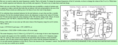
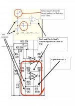
I’m trying to mod the HF and LF EQ section of my mixing console. After research and consulting people with good knowledge in this matter, I reckon I can put two extra Caps. in parallel with C12 by using an ON-OFF-ON toggle switch in order to get 12, 8 and 5 KHz instead of the fixed 10KHz I currently have. The LF seems to be a bit more tricky. It seems to be based on a “gyrator” circuit similar to the one shown on the Forsell Technologies site. As stated on the sheet left of the diagram, removing or shorting Cap. “CS” will turn the circuit into a LF shelf filter, which seems to be the case in my desk’s diagram. Now, I have doubts on what to do next. Put two different Caps. in parallel with C13, via a switch to select three different Low frequencies or put a variable resistance (1M potentiometer) in series with R28 or R29 (don’t know which) to get fully variable choice of Low Frequencies, as shown on the “Gyrator explained” sheet .First is that possible or have I misunderstood the “Gyrator explained”.
Can anyone help Please.
Attachments
Hello, Is anybody out there?
Not many people seem to have a clue about what I'm trying to do.
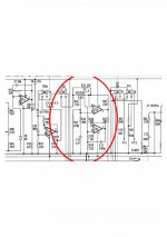
I can see not many people have seen the file containing my desk schematics(well only 3).It's a 14 Channels Old broadcast English desk with some "Belclere" input transformers on every channel.I'm working on the HF and LF section (i'm happy with the semi-para. Mid's band).I want more Frequency choices on HF and perticularely on LF. Now,cap 12 and 13 changes or Potentiometre for continuous Frequency sweep on LF??? And if yes how to wire that??? Any ideas or help would be welcome>
Please,for the love of the children,
Have a look at these.
Not many people seem to have a clue about what I'm trying to do.
I can see not many people have seen the file containing my desk schematics(well only 3).It's a 14 Channels Old broadcast English desk with some "Belclere" input transformers on every channel.I'm working on the HF and LF section (i'm happy with the semi-para. Mid's band).I want more Frequency choices on HF and perticularely on LF. Now,cap 12 and 13 changes or Potentiometre for continuous Frequency sweep on LF??? And if yes how to wire that??? Any ideas or help would be welcome>
Please,for the love of the children,
Have a look at these.
Attachments
Hi,
The tone controls seem rather unusual.
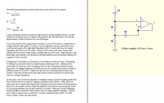
You need to vary the two capacitors in value, you are right, the LF section is a gyrator, the HF section simplemRC shelf. Capacitance needs adjusting in either case to change frequencies, following the usual principle (halve the capacitance double the corner frequency etc...)
Ciao T
The tone controls seem rather unusual.
I'm working on the HF and LF section (i'm happy with the semi-para. Mid's band).I want more Frequency choices on HF and perticularely on LF.
You need to vary the two capacitors in value, you are right, the LF section is a gyrator, the HF section simplemRC shelf. Capacitance needs adjusting in either case to change frequencies, following the usual principle (halve the capacitance double the corner frequency etc...)
Ciao T
Al last a reply
Thanks to ThorstenL,
at last someone with an idea on what's going on here.I was starting to doubt the DIYaudio name of this forum.I will proceed to the change of Caps. 12 and 13 and keep you informed on my progress, thanks again.
By the way, the transformers used in the input section of this desk,I found out, are Belclere and were used for a short time in some of the Neve modules in the 70's.The company is now called OEM (i think).Next step recap and change faulty IC chips on the channels.
Thanks again.
- Status
- This old topic is closed. If you want to reopen this topic, contact a moderator using the "Report Post" button.