If I were to replace these with electrolytic capacitors, I assume I would wire the minus side of the input cap to the base of the transistor and the plus side of the output cap to the collector of the transistor.
Input capacitor... what's the DC volts on the base of TR1 ? and what is the DC volts on the "input" connection which is R1 ?
It's always assumed unless explicitly stated, that whatever you connect an amplifier input to (CD player, tuner, tape deck etc), that that source component will have no DC voltage present.
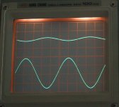
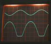
Some 'scope shots then. This is the simple circuit you show in post # 28
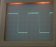
The supply voltage is approx 10 volts and the frequency is 10khz.
The input is the top trace and the output is the lower.
Picture 1 shows the amp with 200 mv peak to peak (pk/pk) applied to the input. The output is approx 1.7 volts pk/pk approx. Any loading on the collector (the 100k) and whatever you connect it too reduces the gain as that change in impedance has to be taken into account. And you have some feedback due to the bias resistor.
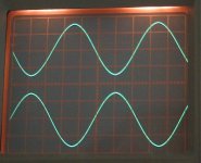
Picture 2 shows more clearly the 180 degree phase inversion that the common emmiter amp produces.
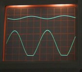
Picture 3 shows a problem. Assymetric clipping. This is due to the bias being less than optimal. With a high impedance simple bias network the characteristics of the transistor have a real effect. Normally in a design it doesn't matter if the transistors have a gain of say 60 or 600... the circuit should be totally unaffected. So here you need a two resistor bias network to give a precise defined reference voltage and at a low enough impedance that the transistor base current is many magnitudes smaller than the current in the bias network and can thus be discounted. The maximum undistorted output here is only 3 volts pk/pk.
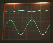
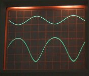
Picture 4 shows a 100 k added from the base to ground to alter the bias. Now the maximum output is nearly 7 volts pk/pk.
Picture 5 shows the LED replacing the 1k resistor. The gain approaches 100 at low input levels below clipping. As the amp is overdriven you can see the distortion produced.
Picture 6 shows effect of a 330k resistor from base to ground, again altering the bias. If you look closely there is some "thickening" of the trace at the lower part... a sign of high frequency instability.
The supply voltage is approx 10 volts and the frequency is 10khz.
The input is the top trace and the output is the lower.
Picture 1 shows the amp with 200 mv peak to peak (pk/pk) applied to the input. The output is approx 1.7 volts pk/pk approx. Any loading on the collector (the 100k) and whatever you connect it too reduces the gain as that change in impedance has to be taken into account. And you have some feedback due to the bias resistor.
Picture 2 shows more clearly the 180 degree phase inversion that the common emmiter amp produces.
Picture 3 shows a problem. Assymetric clipping. This is due to the bias being less than optimal. With a high impedance simple bias network the characteristics of the transistor have a real effect. Normally in a design it doesn't matter if the transistors have a gain of say 60 or 600... the circuit should be totally unaffected. So here you need a two resistor bias network to give a precise defined reference voltage and at a low enough impedance that the transistor base current is many magnitudes smaller than the current in the bias network and can thus be discounted. The maximum undistorted output here is only 3 volts pk/pk.
Picture 4 shows a 100 k added from the base to ground to alter the bias. Now the maximum output is nearly 7 volts pk/pk.
Picture 5 shows the LED replacing the 1k resistor. The gain approaches 100 at low input levels below clipping. As the amp is overdriven you can see the distortion produced.
Picture 6 shows effect of a 330k resistor from base to ground, again altering the bias. If you look closely there is some "thickening" of the trace at the lower part... a sign of high frequency instability.
Attachments
Last edited:
Hello Mooly,
Thank you! This is great. Please allow me some time to study all of this.
Best regards,
Obe1
You are welcome.
It's interesting that you found the sound of the LED version "more alive". I'm guessing you never drove it quite into clipping... that really would sound horrendous... but up to that point, well perhaps subjectively it "had a certain something about it"
")
I found this for you,
http://www.geofex.com/effxfaq/distn101.htm
Mooly,
you are a champion.
Keep up the good work for as long as you have the enthusiasm.
Thanks Andrew... it was a bit of light relief tbh... I'm lacking inspiration putting my germanium headhone amp onto a PCB.
It's slowly getting there though, I hope.
Hi Mooly,
1st: I second Andew's comment!
2nd: Thank you for the article on distortion. It's now a permanent addition to my reference library.
3rd: With, or without the LED, I've not been able to detect any audible distortion (even with the MP3 player set to maximum output).
4th: As life allows, I'm hoping to add the emitter follower stage back in today and play around with some of CCS ideas you presented.
Take care,
Obe1
Hello Mooly and company,
Well, I added the Emitter-Follower (EF) stage back in today and it's being fed with 3mA of current using the (LED based) CCS circuit Mooly suggested. While my ears can't detect that it did anything positive, I didn't detect anything negative either. For that reason (and I get one more pretty light) the EF stage stays in. Please see attached sketch below.
So, what do you all suggest I explore next?
CBS240 suggested bigger coupling capacitors. I'm OK with that, but the only thing in stock locally are gigantic motor starting caps (if I need to stick with a film type cap) or aluminum electrolytic's. Anything else will require mail order (which is OK too).
How about adding another stage to make the whole amp non-inverting? Gosh knows I don't need any more gain, but maybe their's something magical about non-inverting amps I don't understand.
I'm open to ideas.
Thank everyone!
Attachments
Hello Mooly and company,
Well, I added the Emitter-Follower (EF) stage back in today and it's being fed with 3mA of current using the (LED based) CCS circuit Mooly suggested. While my ears can't detect that it did anything positive, I didn't detect anything negative either. For that reason (and I get one more pretty light) the EF stage stays in. Please see attached sketch below.
So, what do you all suggest I explore next?
CBS240 suggested bigger coupling capacitors. I'm OK with that, but the only thing in stock locally are gigantic motor starting caps (if I need to stick with a film type cap) or aluminum electrolytic's. Anything else will require mail order (which is OK too).
How about adding another stage to make the whole amp non-inverting? Gosh knows I don't need any more gain, but maybe their's something magical about non-inverting amps I don't understand.
I'm open to ideas.
Thank everyone!
Are you building all these on a plug board ? (no soldering)
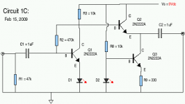
What next... how about a two transistor gain stage using an NPN and a PNP device. It's very different to "just adding another stage" as the two devices work "as one" as it were.
Have a look at the circuit here.
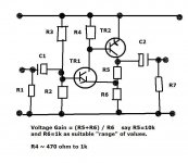
I'll let you "calculate" the bias resistors.
Remember for maximum voltage swing the collector of the PNP transistor wants to be at half the supply voltage approximately.
Hint... so put a value in for the supply, say 10 volts, and calculate the voltages across R5 and R6
Now you know what voltage the emitter of the NPN will be at (ve).
So what voltage does the bias network need to provide at the base of TR1 (vb) ?
Answer... TR1 vb equals TR1 ve + "something"
Aluminium electroylitics are perfect for applications like this.
If you order a few parts I would recommend getting any small signal transistors that keep to the same pinout as you are used to now for the 2N2222.
"Something magical about non inverting amps"...
when using opamps it's my prefered configuration due to there being "no common mode voltage" seen between the two opamp inputs.
Get a TL071 and try it
If you get a 100k preset pot you can play around with opamps at DC and measure the gain etc on your meter... see how it all works. The pot will let you set different inputs up without keep changing parts.
Attachments
Hello Mooly,
Construction: Yes, everything I've wired up so far is on a plugboard (no soldering). Yet soon I would like to take one of my circuits and solder it together on a chunk of perfboard to create a finished/usable project. I've never tried that before either, but interested to see if I can pull it off.
Circuit Quiz: So 5Vdc at collector of TR2 means 0.45Vdc at emitter of TR1 when R5 is 10K and R6 is 1K. Then 0.455Vdc plus a "something" of around 0.65Vdc, means base of TR1 is sitting at 1.105Vdc. With R4 selected to give about 1mA through TR1, I want current through R3 and R2 to be about 0.2mA (assuming conservative Beta of 50 for TR1 and desire for biasing resistors to carry 10 times TR1 base current). So, 10Vdc supply divided by 0.2mA means I want R3 + R2 to be 50K Ohms or a bit less. With R3 at 39K and R2 at 5.1k, total is 44.1K and bias on TR1 will be 1.156Vdc, which is pretty close to the 1.105Vdc target. How did I do professor?
Capacitors: Good to hear that electrolytic caps will be OK.
TL071: Yes, I want to go find some. Anxious to experience "transconductance" without lethal voltages.
----
Now, just got to find time to parts shopping.
Take care,
Obe1
Hi Obe1,
Well that all looks pretty spot on to me at a first look through... I hadn't calculated any values this morning when I drew the circuit... so you have saved me the job
Your figure of 50 for the gain (hfe) of TR1 is good... very conservative so no problems there.
R4... that's an odd one. You say you will select it to give a current through TR1 of 1ma or so. The base emitter junction of TR2 means R4 can never see more than 0.6 volts or so and the emitter of TR1 is at .455 volts. So the combined current of TR1 and the current through R5 give 0.45ma total. The circuit will actually work without R4. R4 helps speed things up by removing charge from the base of TR2 (so called charge storage effects).
I'm sure you would get on fine with strip board... that's how I started
How did I do professor?
Oh yes...you did good !
This is useful to know about transistor currents. Perhaps you have come across this already.
Ie = Ib+Ic
Ib = Ie-Ic
Ic = Ie-Ib
Do you understand R4 ?
Selecting it's value is a "balancing act". The limit of 0.6 volts that can ever appear across it means that if you lower it to much then the circuit just stops working as you starve TR2 of base current because the resistor chain R5 and R6 are determining the available current.
You could drop the value of these, say to 1000 ohm and 100 ohm, but the trade off is increased current draw (when it's not really needed) and increased power dissipation in TR2. The bias network would still be correct... as long as TR1 hfe (beta
) was sufficient. If not you just decrease the value of these to compensate.Now you can add an emitter follower to this amp if you wish (this amp is non inverting by the way).
Got to disappear shortly...
Hi Mooly,
While I did recognize that the voltage across R4 was set/locked by the Vbe (say 0.6V) of TR2, I overlooked that R6 had already pretty much established the current flow through TR1 to just 0.45mA. I allowed myself to get suckered in by the suggestion on the schematic that R4 could be somewhere in the range of 470 to 1000 Ohms (or 0.6/470 = 1.28mA to 0.6/1000 = 0.6mA)., so I just picked 1mA as a nice easy number to work with.
While I did recognize that the voltage across R4 was set/locked by the Vbe (say 0.6V) of TR2, I overlooked that R6 had already pretty much established the current flow through TR1 to just 0.45mA. I allowed myself to get suckered in by the suggestion on the schematic that R4 could be somewhere in the range of 470 to 1000 Ohms (or 0.6/470 = 1.28mA to 0.6/1000 = 0.6mA)., so I just picked 1mA as a nice easy number to work with.
Hello Mooly,
Upon further reflection, I failed the "Circuit Quiz" miserably!
If I assume the current through R6 is set at 0.455mA, that means that zero current (or something close to zero current) is flowing through R5 and the collector of TR2), which would render the circuit inoperative. Despite numerous attempts to resolve this conflict, I'm lost. I suspect that the answer lies in the assumption (or mis-assumption) that just because I desire for the collector voltage of TR2 to be 5Vdc, does not mean that what's TR2 will automatically obey just because I desire it to be that way.
On a happier note, this afternoon I replaced the 1.0uF coupling capacitors with 10.0uF electrolytic caps and the results were phenomenal! Not only did the bass frequencies reveal themselves with more authority, everything I heard through my loudspeakers was much more enjoyable. Marvelous! Simply marvelous! Since I don't have golden ears, I've confined my evaluations of sonic performance of various circuit "tweaks" by playing music where vocalists play the primary role. While I can't always tell when a given musical instrument is "spot on", I have an easier time evaluating when a human voice sounds as it should.
Wow! All of this from a few NPN transistors based on 40 year old technology.
Thank you everyone
Upon further reflection, I failed the "Circuit Quiz" miserably!If I assume the current through R6 is set at 0.455mA, that means that zero current (or something close to zero current) is flowing through R5 and the collector of TR2), which would render the circuit inoperative. Despite numerous attempts to resolve this conflict, I'm lost. I suspect that the answer lies in the assumption (or mis-assumption) that just because I desire for the collector voltage of TR2 to be 5Vdc, does not mean that what's TR2 will automatically obey just because I desire it to be that way.
On a happier note, this afternoon I replaced the 1.0uF coupling capacitors with 10.0uF electrolytic caps and the results were phenomenal! Not only did the bass frequencies reveal themselves with more authority, everything I heard through my loudspeakers was much more enjoyable. Marvelous! Simply marvelous! Since I don't have golden ears, I've confined my evaluations of sonic performance of various circuit "tweaks" by playing music where vocalists play the primary role. While I can't always tell when a given musical instrument is "spot on", I have an easier time evaluating when a human voice sounds as it should. Wow! All of this from a few NPN transistors based on 40 year old technology.
Thank you everyone
Hi Obe1,
You haven't failed at all... building and experimenting is what it's all about. You'll learn infinitely more doing this than just simulating circuits.
Can you see why swapping the 1uf caps for 10uf gave more bass ?
And back to the two stage amp... hopefully I will have time to come back to this today and pull the theory and practical aspects apart.
Hello Mooly,
 Regarding bass response:
Regarding bass response: Since the coupling capacitors and the impedance of the upstream circuitry form a high bandpass filter that attenuates low frequencies, I must have underestimated the actual impedance(s). Especially on the input impedance of my common-emitter circuit, as that's where the increased capacitance delivered the most noticeable impact on performance.
Take care! Bye for now.
First an apology... I have given you some very misleading info on the two transistor amp. The info I gave regarding bias really only holds true when R4 isn't present.
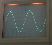
In all these shots the amp was as previously drawn, but using a 12 volts supply.
The first shot shows the amp with no R4... the collector of TR2 is set to 6 volts (I substituted R2 with a 100k multi turn pot to make quick bias adjustments). This is the condition that allows maximum swing at the collector of TR2... and as can be seen there is over 10 volts pk/pk available.
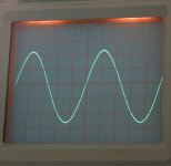
Next up is R4 at 470 ohm. This "lifts" the emitter of TR1 from 0.54 volts with no R4, to around 1.71 volts. The maximum output is now only around 9 volts pk/pk.
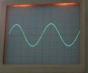
And thirdly with R4 at 180 ohm. Now the emitter if TR1 is at around 3.56 volts. The maximum output is also greatly reduced to around 6 volts pk/pk.
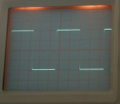
The lower values for R4 give a greatly increased bandwidth. Look at the squarewave shots for no R4 and R4 at 180 ohm. The frequency here is 10Khz. Note the increased and assymetric slew rate.
In all these shots the amp was as previously drawn, but using a 12 volts supply.
The first shot shows the amp with no R4... the collector of TR2 is set to 6 volts (I substituted R2 with a 100k multi turn pot to make quick bias adjustments). This is the condition that allows maximum swing at the collector of TR2... and as can be seen there is over 10 volts pk/pk available.
Next up is R4 at 470 ohm. This "lifts" the emitter of TR1 from 0.54 volts with no R4, to around 1.71 volts. The maximum output is now only around 9 volts pk/pk.
And thirdly with R4 at 180 ohm. Now the emitter if TR1 is at around 3.56 volts. The maximum output is also greatly reduced to around 6 volts pk/pk.
The lower values for R4 give a greatly increased bandwidth. Look at the squarewave shots for no R4 and R4 at 180 ohm. The frequency here is 10Khz. Note the increased and assymetric slew rate.
Attachments
- Status
- This old topic is closed. If you want to reopen this topic, contact a moderator using the "Report Post" button.
- Home
- Source & Line
- Analog Line Level
- Basic Common Emitter Amp Help