I apologize if i missed it somewhere but I have been searching high and low through Google, endless forums, and so forth trying to figure this one out. Either it is so darn simple that it is right in front of my face and I missed it or the information is next to impossible to find.
I am trying to custom design my tube amp to go into a dummy load and from there into a SS power amp or other line level device. All of the schematics I find that have dummy loads go nowhere but end there. They seem to have a switch to go to line out for sound or to dummy load for testing or what have you but no output. What does it take to go from a resistive dummy load to a line level in order to plug straight into an amp, fx unit, eq, etc.?
Thanks in advance")
I am trying to custom design my tube amp to go into a dummy load and from there into a SS power amp or other line level device. All of the schematics I find that have dummy loads go nowhere but end there. They seem to have a switch to go to line out for sound or to dummy load for testing or what have you but no output. What does it take to go from a resistive dummy load to a line level in order to plug straight into an amp, fx unit, eq, etc.?
Thanks in advance
Take the output of the amps in watts RMS... say 10 and decide what dummy load you want, say 16 ohms.
So you can now find the voltage the amp puts out.
That equates to W=Vsqrd/R so rearranging gives V = sqr root W*R which is 12 volts approx (RMS)
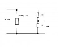
So if you need 1 volt RMS to feed into another device, you need a divider that gives a drops 9 volts across the "top" half and 1 volt across the "bottom" half, so a 90 ohm and 10 ohm or a 900 ohm and 100 ohm etc would be fine.
But it's all so non critical I would use something like a 10K and a 1K in that example.
Make them too low and they dissipate power (so you need bigger than 0.5watt etc) make them too high and the "output impedance" of the divider is high and may be affected by capacitive loading on the device you are connecting too.
You could also fit a 2k2 pot in place of the 1K and find the ideal value by that way, then just measure and replace with a fixed resistor of the nearest value.
So you can now find the voltage the amp puts out.
That equates to W=Vsqrd/R so rearranging gives V = sqr root W*R which is 12 volts approx (RMS)
So if you need 1 volt RMS to feed into another device, you need a divider that gives a drops 9 volts across the "top" half and 1 volt across the "bottom" half, so a 90 ohm and 10 ohm or a 900 ohm and 100 ohm etc would be fine.
But it's all so non critical
I would use something like a 10K and a 1K in that example.Make them too low and they dissipate power (so you need bigger than 0.5watt etc) make them too high and the "output impedance" of the divider is high and may be affected by capacitive loading on the device you are connecting too.
You could also fit a 2k2 pot in place of the 1K and find the ideal value by that way, then just measure and replace with a fixed resistor of the nearest value.
Attachments
Great info Mooly! Sorry I just now caught your post. I have been away from the forum for quite a while. Actually ever since I got the thing working lol! I am currently using this method :
http://www.singlecoil.com/docs/out.pdf
But I have pots where the resistors are so I can find the values I prefer. I still cannot figure out what exactly is doing what. For instance, what is the difference between changing the value on the resistance going out from one jack to the other, vs changing the resistance from the other jack to ground? Anyone know this? It seems to have more sustain and guts when I turn the resistance all the way down between the two jacks and from there work with the resistance to ground vs doing it the other way around.
The two resistors just form a divider. If you have presets and turn the "560" ohm to zero, then turn the "100 ohm" down you will probably damage/burn out the pots. They will probably only be rated for perhaps 50 to 100 milliwatts max.
Keeping the values low as in your link minimises the output impedance... which if feeding the input to any "normal" amp isn't an issue within reason.
Keeping the values low as in your link minimises the output impedance... which if feeding the input to any "normal" amp isn't an issue within reason.
Take the output of the amps in watts RMS... say 10 and decide what dummy load you want, say 16 ohms.
So you can now find the voltage the amp puts out.
That equates to W=Vsqrd/R so rearranging gives V = sqr root W*R which is 12 volts approx (RMS)
So if you need 1 volt RMS to feed into another device, you need a divider that gives a drops 9 volts across the "top" half and 1 volt across the "bottom" half, so a 90 ohm and 10 ohm or a 900 ohm and 100 ohm etc would be fine.
But it's all so non critical
Make them too low and they dissipate power (so you need bigger than 0.5watt etc) make them too high and the "output impedance" of the divider is high and may be affected by capacitive loading on the device you are connecting too.
You could also fit a 2k2 pot in place of the 1K and find the ideal value by that way, then just measure and replace with a fixed resistor of the nearest value.
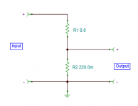
Is there any reason (apart from a slight impedance variation) why you couldn't just use a small value resistor (0.22 ohm) in the bottom leg of the dummy load and take the output from that?
Attachments
It's Attack of the Zombie Threads again... 
Not to mention that voltage coefficient of dummy load and sense resistor may not match, so this approach may be unsuited for accurate amplifier distortion measurements.
By contrast, if you want to measure at 100 w / 8 ohms and need 2 Vrms out, the whole chain of 27k / 2k will dissipate only 27.5 mW while being plenty adequate for the noise level of even relatively good high level inputs (SNR ~128 dB), and you could still go down to something like 5k6/390R or (5k6||5k6)/200R for lower noise into a microphone input when measuring noise levels on a low-noise power amp, particularly when you intend to double output impedance for an accurately balanced output.
Ever thought of power dissipation? For a 100 W load that would have to dissipate ~2.5 W, so you'd need a 3-5 W resistor.Is there any reason (apart from a slight impedance variation) why you couldn't just use a small value resistor (0.22 ohm) in the bottom leg of the dummy load and take the output from that?
Not to mention that voltage coefficient of dummy load and sense resistor may not match, so this approach may be unsuited for accurate amplifier distortion measurements.
By contrast, if you want to measure at 100 w / 8 ohms and need 2 Vrms out, the whole chain of 27k / 2k will dissipate only 27.5 mW while being plenty adequate for the noise level of even relatively good high level inputs (SNR ~128 dB), and you could still go down to something like 5k6/390R or (5k6||5k6)/200R for lower noise into a microphone input when measuring noise levels on a low-noise power amp, particularly when you intend to double output impedance for an accurately balanced output.
Last edited:
It's Attack of the Zombie Threads again...
haha! I knew it was an old thread, but it came up in the search so seemed pointless to start a new one.
Ever thought of power dissipation? For a 100 W load that would have to dissipate ~2.5 W, so you'd need a 3-5 W resistor.
Yes, I considered this, but 0.22 ohm 5w resistors are plentiful and cheap.
Not to mention that voltage coefficient of dummy load and sense resistor may not match, so this approach may be unsuited for accurate amplifier distortion measurements.
So that's the "catch 22" - I did wonder.
I
By contrast, if you want to measure at 100 w / 8 ohms and need 2 Vrms out, the whole chain of 27k / 2k will dissipate only 27.5 mW while being plenty adequate for the noise level of even relatively good high level inputs (SNR ~128 dB), and you could still go down to something like 5k6/390R or (5k6||5k6)/200R for lower noise into a microphone input when measuring noise levels on a low-noise power amp.
Yes, I'm already using a 12k / 470 ohm divider as per a couple of posts above.
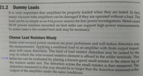
I was curious, as in his book 'Designing Audio Power Amplifiers' Bob Cordell suggests using a low value resistor as per my suggestion to verify a dummy load. (see paragraph in attachment)
Attachments
Not exactly a deep reason, given the resistor divider you replace would probably be a power device for the top resistor anyway for low output impedance.It's Attack of the Zombie Threads again...
Ever thought of power dissipation? For a 100 W load that would have to dissipate ~2.5 W, so you'd need a 3-5 W resistor.
Highly unlikely as they will both be wirewound power resistors which are essentially free from distortion. Worry about steel terminal posts first.Not to mention that voltage coefficient of dummy load and sense resistor may not match, so this approach may be unsuited for accurate amplifier distortion measurements.
One issue that is real is the ground IR voltages between amp and dummy load will be substantial. Thus the ground coming out of the dummy-load/divider box will be different between the channels.
Also if the amp going into the dummy load is bridged, none of this works.
- Status
- This old topic is closed. If you want to reopen this topic, contact a moderator using the "Report Post" button.
- Home
- Source & Line
- Analog Line Level
- Dummy load with output to power amp