(ducking and covering my head ...)
I've heard the Carver Sonic Holography sound beneficial in some situations. Unfortunately, it's embedded in my Carver Preamp, which isn't that good - it's a little noisy and has wayyy too much gain. I'd like to build a high-quality stand-alone module (put it inside an old Musical Fidelity "can").
I found a few sparse discussions on this forum, but no hard details. Anyone have a schematic, or know where to find one to make a DIY clone?
(ducking and covering my head ...)
You better
") , The circuit used some pretty junky parts which included one of those very early Motorola multiplier/modulators hence the noise. IMHO there are simpler circuits that make these interesting effects. Check online patents maybe.
, The circuit used some pretty junky parts which included one of those very early Motorola multiplier/modulators hence the noise. IMHO there are simpler circuits that make these interesting effects. Check online patents maybe.You better
Possibly one of the reasons that when we brought the 1st of these devices in (late 70s), they quickly got dubbed (and are still called today) "Sonic Holocaust"
dave
I found the schematics at The Carver Site.
Yea, I'm not particularly impressed with the preamp. It's noisy and has way too much gain. Looking at the schematic, there's an extra +16dB gain block inserted into the signal path. The only reasonable explanation it is designed to operate the volume knob no greater than 9:00 position.
Since the preamp is one of my "workhorse" pieces (used while testing amps), I'll break out the soldering iron and bypass the gain block later this week.
Yea, the parts selection isn't stellar. OK, the parts selection is horrible ... but the idea is interesting nonetheless. I'm debating if the idea is interesting enough to create my own DIY version, possibly simplifying it a bit (but still based on the original theory). In the original Carver equipment, it's too poorly implemented to have decent sound quality.
I was listening to it this evening. The "sonic hologram" created a total (catastrophic) mess to some recordings. I suspect those recordings already had some preprocessing performed at the studio. For example, maybe Sonic Hologram has a terrible conflict with recordings made with BBE Sonic Maximizers, or other similar studio processors. So the Sonic Hologram is highly sensitive to the recording, particularly if the recording had preprocessing applied in the studio.
However, some recordings were fantastic and more engaging. The soundstage extended well beyond the speakers. Not quite 180 degrees, but a lot. Well executed, the Sonic Hologram theory would bring more enjoyment to my listening experience (with the right style of music and recording).
... listening and enjoying is what it's all about, right?
The circuit used some pretty junky parts ...
Yea, I'm not particularly impressed with the preamp. It's noisy and has way too much gain. Looking at the schematic, there's an extra +16dB gain block inserted into the signal path. The only reasonable explanation it is designed to operate the volume knob no greater than 9:00 position.
Since the preamp is one of my "workhorse" pieces (used while testing amps), I'll break out the soldering iron and bypass the gain block later this week.
... they quickly got dubbed (and are still called today) "Sonic Holocaust" ...
Yea, the parts selection isn't stellar. OK, the parts selection is horrible ... but the idea is interesting nonetheless. I'm debating if the idea is interesting enough to create my own DIY version, possibly simplifying it a bit (but still based on the original theory). In the original Carver equipment, it's too poorly implemented to have decent sound quality.
I was listening to it this evening. The "sonic hologram" created a total (catastrophic) mess to some recordings. I suspect those recordings already had some preprocessing performed at the studio. For example, maybe Sonic Hologram has a terrible conflict with recordings made with BBE Sonic Maximizers, or other similar studio processors. So the Sonic Hologram is highly sensitive to the recording, particularly if the recording had preprocessing applied in the studio.
However, some recordings were fantastic and more engaging. The soundstage extended well beyond the speakers. Not quite 180 degrees, but a lot. Well executed, the Sonic Hologram theory would bring more enjoyment to my listening experience (with the right style of music and recording).
... listening and enjoying is what it's all about, right?
Boy, I don't understand what Carver was doing with his preamps.
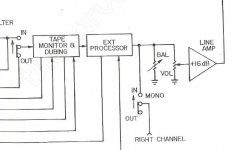
First, the preamp has a +16dB "line amp" gain block, which gives the unit too much gain (see block diagram picture below).
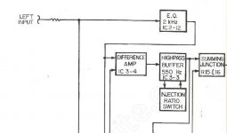
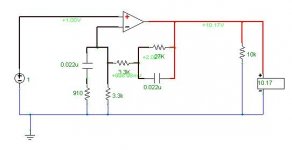
Then the sonic hologram circuit begins with an op-amp 2kHz EQ (block diagram IC2-12 and schematic pictures attached below) that adds another whopping +20dB (of course, this is preceded by a mild voltage divider).
If I'm gong to build a DIY sonic hologram, I don't need the gain. What is it with these consumer electronic guys and their "gain poisoning"?
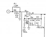
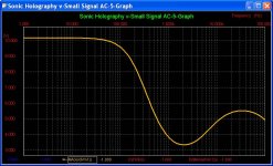
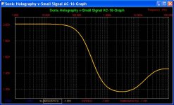
Anyway, I simulated the offending 2kHz EQ. The gain is coming from the 27K resistor in the negative feedback loop. This is an obvious recipe for high gain, when the other resistor is 3.3K. Pictured below is the response characteristics (in units of magnitude, V/V gain).
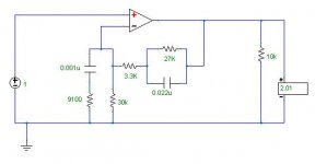
So I changed the 3.3K grounding resistor to 30K, and also made adjustments to the accompanying RC network (adds a hump at 13kHz). This lowered this block's gain from +20dB to +6dB, while retaining similar response characteristics (not exact, but I did it during lunch).
So here is the question:
If the input to the preamp is 1V peak-to-peak music signal (ordinary for CD players, etc.), the +16dB "line amp" block and the +20dB gain in the sonic hologram quickly amplifies the 1V p-p to over the preamp's power supply rails of +/-13VDC, unless the volume knob is kept at a very low position. Is there a reason why the internal signals need to have such high magnitude? Some of the sonic hologram's internal signals reach over 10V (p-p) with a 1V input, nearly clipping the opamps on the power supply rails.
I learned (by experience) that op-amps are more linear when operating at a fraction of their supply voltages (i.e. +/-5V signals with +/-15V power rails). It seems to me that keeping internal signal voltages to reasonable levels is better than operating the opamps near their rails. (although, I have found that opamps work better with high rails, for example, +/-18V rails seem to work better than +/-12V rails, even with small signals below a few volts.)
First, the preamp has a +16dB "line amp" gain block, which gives the unit too much gain (see block diagram picture below).
Then the sonic hologram circuit begins with an op-amp 2kHz EQ (block diagram IC2-12 and schematic pictures attached below) that adds another whopping +20dB (of course, this is preceded by a mild voltage divider).
If I'm gong to build a DIY sonic hologram, I don't need the gain. What is it with these consumer electronic guys and their "gain poisoning"?
Anyway, I simulated the offending 2kHz EQ. The gain is coming from the 27K resistor in the negative feedback loop. This is an obvious recipe for high gain, when the other resistor is 3.3K. Pictured below is the response characteristics (in units of magnitude, V/V gain).
So I changed the 3.3K grounding resistor to 30K, and also made adjustments to the accompanying RC network (adds a hump at 13kHz). This lowered this block's gain from +20dB to +6dB, while retaining similar response characteristics (not exact, but I did it during lunch).
So here is the question:
If the input to the preamp is 1V peak-to-peak music signal (ordinary for CD players, etc.), the +16dB "line amp" block and the +20dB gain in the sonic hologram quickly amplifies the 1V p-p to over the preamp's power supply rails of +/-13VDC, unless the volume knob is kept at a very low position. Is there a reason why the internal signals need to have such high magnitude? Some of the sonic hologram's internal signals reach over 10V (p-p) with a 1V input, nearly clipping the opamps on the power supply rails.
I learned (by experience) that op-amps are more linear when operating at a fraction of their supply voltages (i.e. +/-5V signals with +/-15V power rails). It seems to me that keeping internal signal voltages to reasonable levels is better than operating the opamps near their rails. (although, I have found that opamps work better with high rails, for example, +/-18V rails seem to work better than +/-12V rails, even with small signals below a few volts.)
Attachments
- Status
- This old topic is closed. If you want to reopen this topic, contact a moderator using the "Report Post" button.