Yes. DO listen very carefully to everything that GK says, suggests, and implies. He has great knowledge and _much_ useful information.
I forgot to mention that I have sometimes had too many problems when trying to use those white plug-in boards that you have used. It got to the point where it was more time-efficient to simply make printed circuit boards, even just for prototyping. And a PCB can give much better results, even if the protoboard is not having its own problems.
You would need some way to be able to print your PCB layout on a laser printer. And you need some PCB blanks (mouser.com or search for FR4 on ebay.com). But with the method at Easy PCB (Printed Circuit Board) Fabrication, Using Laser Printer Toner Transfer, with a Household Clothes Iron and Glossy Inkjet Photo Paper; DIY at Home; Better AND Cheaper than Press-n-Peel ( PnP / P-n-P )! Making, Cheap , Economical , fastest fas , virtually everything else can be purchased almost anywhere that has civilization. I hate having to wait for something to come in the mail, such as etchant, when I want to fabricate a pcb. So I put together the method described, there. It works well-enough for one-offs and small production runs of one- or two-sided boards. You can go from screen image to finished board in less than an hour.
There are lots of threads, on this site, that descuss the best way to route the traces, etc. I actually used MS Paint to do the artwork, at first. But a dedicated PCB-CAD package is a much better idea. There are threads here that discuss which ones are best, and free ones, etc.
Tom
"One of the first things I learnt when beginning to play with opamps and pots.
Crappy MSpaint pic:
"
I confess to have made the same errors.
Pause for Thought: an op-amp might have a loop gain of >100dB at 50Hz. Its quite easy to pick up 0.5uV over 6" of pcb trace between the feedback resistor junction and the input. Multiply this by 100dB . . . . say goodbye to high fidelity.
Another few:
Using non-unity gain stable op-amps in buffer or low gain circuits. Wonder why it sounds hard 'n harsh? Or 'veiled'? or noisy?
Another classic. Plugging op amps into DIP sockets . . . .without thinking about the comp cap connections (some place the comp cap across pins 5 and 8 . . . and others across 1 and 8 . . ). Of course, this assumes the user understands why a comp cap is needed in the first place.
Decoupling . . . plenty of opportunity to run into problems . . .
Might be a good idea to make a page in the wiki 'Op-Amps for Everyman'
"One of the first things I learnt when beginning to play with opamps and pots.
Crappy MSpaint pic:
"
I confess to have made the same errors.
Pause for Thought: an op-amp might have a loop gain of >100dB at 50Hz. Its quite easy to pick up 0.5uV over 6" of pcb trace between the feedback resistor junction and the input. Multiply this by 100dB . . . . say goodbye to high fidelity.
<snipped>
That also reminded me about why "star"-type grounding is so necessary, sometimes: Suppose you have a ground-return trace that is carrying a 1 Amp sine at 5 kHz (maybe like a speaker's ground return). Suppose that an opamp's or chipamp's input resistor's ground shares that same ground trace (i.e. it's NOT star grounded). If the trace is only four inches long, it might have 100 nH of inductance and 4 mOhms of resistance. Because of V=L(di/dt) and V=IR for the distributed inductance L and resistance R of the trace (or wire) itself (where di/dt is the rate-of-change of the current), the +/- 1 Amp 5 kHz sine current would induce a +/- 5 mV sine voltage, back at the NON-ground end of that trace, and that +/- 5 mV sinusoidally bouncing ground reference would then be arithmetically SUMMED with the opamp's input voltage!!
Another classic. Plugging op amps into DIP sockets . . . .without thinking about the comp cap connections (some place the comp cap across pins 5 and 8 . . . and others across 1 and 8 . . ). Of course, this assumes the user understands why a comp cap is needed in the first place.
That is assuming the op amp in question isn't already internally compensated.
Adding an input transformer
Hi all,
I've resumed my INA217 project after almost one year! I'm going to modify some things on the circuit, that is to replace DC blocking caps with an input transformer particularly to add some color to the sound... I thought to use a transformer with 1:3.5 ratio from Cinemag (CMMI-3.5C) implemented in the way you see on the schematic I attached. With R5 and R6 of 15k the input impedance should be of 2k (differential input impedance seen by the microphone).
Next step is to make a PCB following the guide written by gotee.
I really need your critics and comments!
M.
Attachments
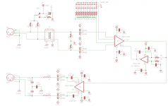
I'm getting a lot of noise (a sort of white noise).
DRV 134 has floating balanced output. In case you take only one output signal, for example OUT+ vs. ground, you will get a lot of noise. You have to use true balanced output, i.e. OUT+ vs. OUT-, then the noise level would be approx. 20dB lower.
Ettos,
I would add a 10 uF electrolytic from each chip power pin to ground.
DC servos are "fun". Not sure these suggestions are needed or applicable (haven't simulated your circuit), but:
- You could add diodes to temporarily greatly speed up the integrator's response when there is a very large DC offset. I'm not sure they would be desirable in this circuit, though.
- You might want a good low-pass filter or two right after the differential integrator.
- You might want a resistive voltage divider, just before the servo output signal goes into the inamp's REF input.
- You will probably want a trimmer or pot, somewhere, to be able to adjust the circuit for zero DC offset at the inamp's output.
Tom
Last edited:
Can-you explain the difference at normal line levels ? They are in serial. Currents are the same in both topologies. Or did-you believe in some magic fighting against the physical laws ? Or Op Amps sympathies to his nearest neighbor ? If it is about noise at very low level can-you provide difference in noise measurement in a well shielded housing and real situation?
Crappy MSpaint pic:
The best sounding way to manage variable resistances is ... to not use them: tune, measure their values and replace them with a metallic resistance of the same value.
Last edited:
Can-you explain the difference at normal line levels ? They are in serial. Currents are the same in both topologies. Or did-you believe in some magic fighting against the physical laws ? Or Op Amps sympathies to his nearest neighbor ? If it is about noise at very low level can-you provide difference in noise measurement in a well shielded housing and real situation?
The best sounding way to manage variable resistances is ... to not use them: tune, measure their values and replace them with a metallic resistance of the same value.
I believe that GK's point was that one should minimize the lead length (and thus the stray capacitance) seen by an opamp's inverting input, to prevent oscillation (and ditto for the instrumentation amp's gain-setting pins).
And if one desires to use a potentiometer or switched resistors, connected to an opamp's inverting input or to an inamp's gain-setting pins, then the pot or switch would typically have to be located some distance away from the chip's pin(s) and in that case a fixed resistor should be placed in series with and very close to the pin(s), to isolate the pin(s) from the stray capacitance of the relatively long wires or traces.
I do agree that it might be best to avoid configuring an opamp for variable gain, using an upstream attenuator, instead.
In the case of the inamp circuit shown in post 27, the switched R values shown would limit the series resistance at each pin (1 and 8) to 4.5 Ohms (while replacing the 9R with zero Ohms and lowing the others by 9 Ohms), which might not be enough but would probably be better than nothing.
Perhaps the inamp's gain could be fixed and an upstream balanced switched attenuator could be devised. But that seems like it might be difficult to implement.
Thank-you for this explanation, i agree.
In my mind, it is more about layout design of the circuit board than witch of two serial elements should be placed first, as some kind of law ;-)
Well, i use exclusively since years current feedback op amps for audio, they are very stable with a good phase margin, even at unity gain, and i was never in concern with stray capacitances issues, despite there >10Mhz bandwidth. So i never asked myself the question, looking at square waves at 100 Khz. of course, when you're about to design a first stage mic preamp, you enter in a quite different world of thoughts and precautions.
What about the mixing bus of a desk ?Most opamps will not tolerate capacitance on the -IN pin.
Isolate that pin from parasitic capacitances by mounting resistor/s to the PIN or very close to the PIN.
;-)))
- Status
- This old topic is closed. If you want to reopen this topic, contact a moderator using the "Report Post" button.
- Home
- Source & Line
- Analog Line Level
- Balanced line driver (DRV134) and noise