Hi to all,
I'm building a microphone preamp based on an INA217 chip.
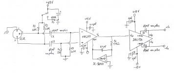
I'm trying to get a balanced output with the DRV134 line driver. I just followed the drv134 datasheet schematic (see the attachment) but I'm getting a lot of noise (a sort of white noise).
The output of ina217 is pretty quiet, all the noise is generated by the drv134.
I tried to remove C4 and C5, and to use different bypass capacitor but... nothing!
Is there anything I can do to solve this? Do you suggest other solutions to get a balanced output?
Thank you very much,
Matteo.
I'm building a microphone preamp based on an INA217 chip.
I'm trying to get a balanced output with the DRV134 line driver. I just followed the drv134 datasheet schematic (see the attachment) but I'm getting a lot of noise (a sort of white noise).
The output of ina217 is pretty quiet, all the noise is generated by the drv134.
I tried to remove C4 and C5, and to use different bypass capacitor but... nothing!
Is there anything I can do to solve this? Do you suggest other solutions to get a balanced output?
Thank you very much,
Matteo.
Attachments
Hi, I'm not sure on this one as the output of your INA217 should be faily low impedance but could your problem be injected noise from the 1M servo resistor.
Also what gain have you set the INA217 for as you want to gain it up at this stage, not pass it to the DRV137 at a low level. The DRV is intended to operate at line level not at microphone levels. Your diagram shows no gain resistors if this is the case then you have a gain of 1 which is not suitable.
Regards,
Andrew
Thank you for your answer, Andrew.
It's not the 1M resistor. I tried disconnecting the whole servo and the noise remains.
The gain of the INA is regulated by a potentiometer. For recording guitar with a condenser microphone, for example, I set a gain of 65 (150 Ohm resistance).
Regards,
M.
It's not the 1M resistor. I tried disconnecting the whole servo and the noise remains.
The gain of the INA is regulated by a potentiometer. For recording guitar with a condenser microphone, for example, I set a gain of 65 (150 Ohm resistance).
Regards,
M.
Make sure you have both sides of the differential output loaded. Don't leave either of them open-circuited. Maybe try something close to 600 ohms on each output.
I've seen this same problem as well but didn't look into it too closely at the time. I'll be interested in your results.
I've seen this same problem as well but didn't look into it too closely at the time. I'll be interested in your results.
Last edited:
Make sure you have both sides of the differential output loaded. Don't leave either of them open-circuited.
Yes, the output is connected to a pc audio interface (balanced input). I can actually hear the noise.
Thank you paulb,
M.
Hi, Sounds like you have tried most of the obvious things.
How good is your decoupling could it be unstable?
Regards,
Andrew
Actually I don't know because I haven't got an oscilloscope to test it at present. I used variuos bypass capacitor with no improvements.
This is the power supply unit I use PSU-2448mk2 Kit
Good night,
Matteo.
Its unlikely that the PSU regulation would cause noise of this type. I was referring more to the local decoupling; you show some local 1uF caps on the DRV this decouping very close to the supply pins and be a high speed dielectric (i.e not a electrolytic). Although to be honest instability doesn't normally cause a white noise sound, it usually just heats the device up with ultrasonic oscillation.
I am out of ideas. If it is unstable you can normally stop this by touching the circuit. It may inject a bit of hum but it usually stop the oscillation so you could try just touching areas on the circuit to see if you can find a sensitive node.
Regards,
Andy
I am out of ideas. If it is unstable you can normally stop this by touching the circuit. It may inject a bit of hum but it usually stop the oscillation so you could try just touching areas on the circuit to see if you can find a sensitive node.
Regards,
Andy
Often, if it sounds like white noise it is in fact high frequency oscillation (200KHz and above). I am not familiar with the balanced line drive r you are using, but it might be you have a capacitive load on the output (figure on 100pf per metre of cable, sometimes higher) and its causing the buffer to go unstable. Additionally, if you are feeding into a sound card, the sound card may have RF decoupling caps from the input to ground designed to work at above audio, but nevertheless causing loading problems in op-amps and buffers. Try inserting a 100 Ohm resistor in series with each output of the driver IC. Place the resistors close to the IC. Can you post a photograph of your layout/setup?
Also, keep in mind that you may have a lot of RF hash around because of the PC - power supply, CPU clock etc - that could be causing problems.
Also, keep in mind that you may have a lot of RF hash around because of the PC - power supply, CPU clock etc - that could be causing problems.
Last edited:
The DRV134 has 50 ohm build out resistors internally to the chip so he can skip those but I agree on the output of the INA217. If he had a 'scope I bet he'd see some serious oscillation at the output. I would also add some LP filtering on the mic inputs to prevent RF pickup. Ferrite beads can help here. It's really aweful to get out in the field with the recording gear and start picking up stray RF into your audio when there is nothing you can do about it.
Looks like he copied most of the schematic from page 7 of the data sheet but he omitted the 4 protection diodes. It would be better to have them in, especially when turning on the phantom switch with no mic plugged in and probably take out the INA217 in the process.
G²
Looks like he copied most of the schematic from page 7 of the data sheet but he omitted the 4 protection diodes. It would be better to have them in, especially when turning on the phantom switch with no mic plugged in and probably take out the INA217 in the process.
G²
I didn't omit the 4 protection diodes, I haven't just draw them on my sketch...
I tried to put a 100Ohm resistor on the output of the INA217... nothing!
It seems like a "self-generated" white noise, it is constant at any gain setting and it doesn't change if I touch any component. I thought it was a faulty chip, but I also tried another one...
If I can find one I will try a THAT1646 since it is pin-compatible with the DRV134.
It might help to see your actual circuit layout, especially for grounding and power. I would also want RF filters on all inputs and power supply connections. You might find some good suggestions in Walt Jung's Op Amp Applications Handbook, which is on line in its entirety, free, at ADI - Analog Dialogue | Op Amp Applications Handbook .
You should definitely try an approximately-100-Ohms metal film resistor in series between the INA217's output and the DRV134's input. You could even use two resistors of about 50 Ohms each, with about .01 uF to ground from between the two resistors, for added RF filtering in both directions. (Aside: The "T" topology is also good when you're up against an inverting opamp input, since tying capacitance directly to an inverting input can de-stabilize the circuit.)
Are your RF bypass caps connected within 1/4-inch of the power pins? And for the DRV134 you probably also need to add a large, low-ESR electrolytic (probably 470 uF or larger, to get low ESR), with short leads, in parallel with each of the 0.1 uF bypass caps. And the 0.1 uF bypass caps should be low-inductance, such as stacked polyester film types. (Note that the DRV134 datasheet shows a 1.0 uF bypass cap on each power pin, but also states "Decoupling capacitors placed close to the device pins are strongly recommended in applications with noisy or high impedance power supplies.". Note the plural: "capacitors", i.e. more than one. And then read the section on buffers and line drivers in Chapter 6 of Jung's book. I would also add at least a 10uF electrolytic in parallel with the bypass caps on the INA217.
Also, your layout should be in accordance with high-speed rules, with a heavy ground plane, compact layout, attention to signal coupling problems, and should also use star grounding concepts. (Please tell us that the grounds aren't all just daisy-chained together.)
And whoever mentioned adding a low-pass RF filter to the input was absolutely correct. See Section 7-6 of Walt Jung's "Op Amp Applications Handbook", which is on line in its entirety, free to download, at ADI - Analog Dialogue | Op Amp Applications Handbook . It gives a schematic, and the component-value equations, for a flexible, general-purpose common-mode/differential-mode RC EMI/RFI filter for instrumentation amplifier inputs.
You will probably also find to be useful at least the Line Drivers sections of Chapter 6 and the Instrumentation Amplifiers sections of Chapter 2.
Cheers,
Tom
Thank you all for your answers (in particular Tom for his tips and bibliography).
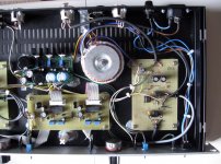
I must admit that the preamp hasn't got a real "layout", I didn't use a serious pcb but I arranged the components on a stripboard (as you can see on the photo... the preamp is on the right side, on the upper left there's the power supply, and the vu-meter on the lower left). Anyway, this is one of my first projects!
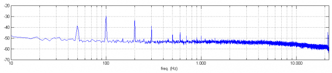
I've also attached an mp3 clip of the (amplified) noise at the output of the DRV134 and the FFT spectrum: it is almost flat with some peaks on 50Hz and its harmonics... When I record it is more than perceptible over the signal.
Regards,
Matteo.
I must admit that the preamp hasn't got a real "layout", I didn't use a serious pcb but I arranged the components on a stripboard (as you can see on the photo... the preamp is on the right side, on the upper left there's the power supply, and the vu-meter on the lower left). Anyway, this is one of my first projects!
I've also attached an mp3 clip of the (amplified) noise at the output of the DRV134 and the FFT spectrum: it is almost flat with some peaks on 50Hz and its harmonics... When I record it is more than perceptible over the signal.
Regards,
Matteo.
Attachments
Very good, for one of your first projects!
I think that what you are hearing should not be called "noise". It is probably "50 Hertz hum" (plus some harmonics of 50 Hz).
One thing that might be contributing to the hum problem is the close proximity and the parallel proximity of AC Mains and signal wires, to each other.
If you can route the wires so that the AC Mains wires (and the transformer secondary's wires, which are also 50 Hz AC) are not close to any other wires (such as DC, signal, or DC or audio ground), that might help a lot.
Also, at the same time, if you can tightly twist together any wire pairs, such as the AC line and neutral, and the transformer secondary wires, and any pairs of corresponding signal and ground or DC and ground wires, that might also help a lot.
If any DC or signal or ground wires "must" cross near any AC wires, they should cross at a right angle (90 degrees/perpendicular), and should never be be close to, and/or parallel with, each other, the AC wiring.
Another situation (partially included above) that can contribute to inducing hum in the audio portions of the circuit is when a signal or DC path and its ground return path are separated, so that their "loop" contains a significant geometric area. Any DC or signal and its corresponding ground return should be run very close together, so they don't "enclose any area" by having space between them. Otherwise any changing magnetic field, such as the ones from an AC transformer, or even AC wiring) can much more easily induce a corresponding AC current in them. That is why I suggested twisting-together any DC or signal wire and its corresponding ground wire, above. But you also need to check whether any pairs like that have been routed far apart from each other, and try to route them together, instead.
If you can correct and thereby eliminate those possible causes of the hum problem, then we can proceed from there, to see if there might also be a grounding-architecture situation that is contributing to the hum.
Tom
The gain of the INA is regulated by a potentiometer. For recording guitar with a condenser microphone, for example, I set a gain of 65 (150 Ohm resistance).
These instrumentation amps are sensitive to stray capacitance presented to the gain set resistor terminals (inverting input nodes). You sometimes only need several pF here to induce enough phase shift to casuse oscillation.
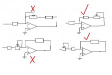
If you're setting the gain with a potentiometer (presumably) located some distance for the chip, it may be necessary to isolate the lead/track capacitance by adding two small value fixed resistors in series with the pot, each resistor being located right at the IC pins.
Last edited:
Actually, this is a hell of a good point raised by GK. Back when I started a few decades ago, I wondered why my LF356 preamp was noisy, oscillated and seemed to pick up all sorts of crap. Well, my feedback resistors were located about 6" from the actual op-amp inverteing pin and I had a long pcb trace making the connection. Always keep the feedback resistors, and especially the junction point, right next to the inverting pin - and I mean right next to it. Ditto for any feedback amplifier.
")
- Status
- This old topic is closed. If you want to reopen this topic, contact a moderator using the "Report Post" button.
- Home
- Source & Line
- Analog Line Level
- Balanced line driver (DRV134) and noise