This thread documents a preamp project I've been contemplating since a little before Burning Amp '09. I'm christening. I'm christening it "The Evil Sandman" because its pristine vacuum state is marred by some bits of nasty silicon. The RIAA portion has remained pretty much static since its conception (triode based, passive equalization), but the lineamp portion has seen quite a few changes as I wrestled with this and that circuit concept. I settled on a non-inverting stage with gain based on a commonly available power pentode.
The picture below shows the first breadboard of the lineamp. I actually powered up up that crazy little cats-cradle of parts just a half hour ago, and the bias voltages look right. When I have time, I'll take a look and see whether it actually makes noises like a lineamp... Schematics will follow when I'm reasonably satisfied. I'll then hammer away at the RIAA preamp.
This project will use all commonly available (at least in the US) 7-pin tubes. More later.
Attachments
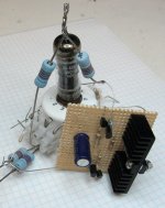
Here's the circuit I'll be using for the line amp. In the rough prototype, Q1 was replaced with a ring-of-two 1mA current sink, but the JFET eliminates a low voltage positive supply that won't be on the real deal. I ran the prototype with a DC filament and a Xantrex HV bench supply. The real supply will involve some sneaky subterfuge with a 50VA dual input 12V + 12V toroidal transformer. More on that when I verify that I can get away with said subterfuge.
Attachments
")
More evil sand. This configuration makes better use of the 10 mA allotted to the tube portion (more transconductance for a given plate current). Despite all the sand scattered about, the tube is the boss. I may omit the input cap and put the volume pot pot (with a safety resistor from wiper to ground) right at the input. Some care may be in order, as these slippery RF tubes are reputed to run a few microamps of grid current even when reversed biased. Anyway, it won't hurt to breadboard the thing to see how it performs.
This amp accomplished several things : low gain, no inversion, and an output voltage centered reasonably close to 1/2 plate voltage for wide dynamic range.
This amp accomplished several things : low gain, no inversion, and an output voltage centered reasonably close to 1/2 plate voltage for wide dynamic range.
Attachments
The previous circuit looks complex, but what is going on is simple, taken a piece at a time. Depletion mode mosfet Q6 sets the total bias current for triode V1 and output Darlington stage Q4-Q5 at 30 mA. This current is sampled by current mirror Q7-Q8, and a 1 mA current (set by ratio of R11 to R12) is passed up to current mirror Q2-Q3. This mirror provides 10 mA (set by ratio of R2 and R7) to the V1 plate, setting its bias current. The rest of the 30 mA bias current must perforce flow through Q4 and Q5.
Using a minus supply at the emitters of Q7-8 allows one freedom in the choice of tubes for V1. In the previous Sandman design, choices were limited by the ground-referred design to tubes that would have sufficient bias volate at a given bias current of 10 mA to provide sufficient headroom and output voltage. The cost of this versatility is capacitors C3 and C4, which block DC from passing through R12.
Since V1 is pinned between two current sources, any disturbance in bias current caused by an input signal is passed directly to Q4-Q5, and is fed back to the cathode of V1 via R9 and R12.
All of this is to obtain a low gain non-inverting buffer with reasonable output impedance. For those who wince at the thought of so much sand sprinkled among the vacuum, an alternate approach might be to use a hefty unity gain buffer driving a modest step-up transformer. This approach could also benefit by some judicious sprinkling of sand. Check out SY's Heretical Lineamp thread to see what I mean. I may try something similar to what he's done later on, as I have some old Jensen line output transformers with nothing to do.
Anyway,the Sandman setup will serve as a test bed for various ideas, just like my solid state preamp box has been for the past 3-4 years.
I've been having more thoughts on the "Evil Sandman concept, and have settled on a unity gain line stage. I'll present two schematics here. One is based on the omnipresent and supremely cheap 6J6. The other is based on triode-pentode pair 6LQ8 and little 7-pin super-pentode 6EW6. First off, the 6J6 circuit. This utilizes the drop of a GaAsP red LED (first-generation dim, deep red LED with 1.6-1.7V drop at 10 mA bias current) to bias and decouple the stages of a passively equalized RIAA amp. The line stage is a current source loaded cathode follower with current sink load using both halves of a 6J6 in parallel. Very simple. I'm eager to find out how it sounds for such a cheap concept. There's some sand, but not as much as the next circuit in the series.
Attachments
This is the next in the series. The RIAA portion is much the same as the previous circuit, except for the choice of the tube, and the absolute decoupling of the two stages of the RIAA preamp. The line stage is another story. The triode connected 6EW6 is helped out by a darlington connected pair, which boosts the effective Gm of the tube. Current sources set the total current drawn by darlington and 6EW6 and help apportion the current between tube and output darlington. Since I can't find curves for the triode-connected 6EW6, I'll have to breadboard the circuit to determine how current will be apportioned between the tube and the darlington-connected transistors. I also don't know the characteristics of the pentode from the 6LQ8 triode-connected. If anyone can help, give a shout. Otherwise, I'll just breadboard it and see.
Attachments
Last edited:
Having leaned a bit in the couple of years since I started this thread, here is a pared-down version of a "Sandman with gain" that I mean to breadboard when I have the time. The Supertex VP0120N5 are long gone ( Supertex doesn't put their smallest die in a TO-220 package any more), but I have a stash, and it's time to use a few rather than just hoard them.
Attachments
Last edited:
Q10 appears twice??? One of them strapped as a diode
drop for the purpose of adding a few volts to Q9's drain?
I'm guessing the plate is immobilized by feedback, at
the VGS threshold of Q10 stacked with Q10, go figure...
and also held at very constant current by Q9 & R14...
If the cathode is moving 1/4 the output swing and Mu
is 9.5, the gain is 4((Mu-1)/Mu) = 3.58? It might be a
little less due to R13, I didn't calculate for R13's effect...
Last edited:
- Status
- This old topic is closed. If you want to reopen this topic, contact a moderator using the "Report Post" button.
- Home
- Source & Line
- Analog Line Level
- "The Evil Sandman" Preamp