I believe this concept is similar to the Technics class AA amps, however I cannot see what benefits is brings with op-amps:
NE5534 + NE5532 CLASS AA OUTPUT LINE LEVEL PREAMPLIFIER on eBay (end time 26-Nov-09 06:03:18 GMT)
Any comments?
NE5534 + NE5532 CLASS AA OUTPUT LINE LEVEL PREAMPLIFIER on eBay (end time 26-Nov-09 06:03:18 GMT)
Any comments?
I am intrigued... and unable to "analyse" it in my head.
It is like the Technics idea and also Aubrey Sandmans Class "S" the idea being to use a second amp to make the main voltage amplifier look like it is working into a higher impedance load.
All my instincts tell me it will not be good for sonics... particularly when you consider the typical loads it will work into anyway.
One of the more intriguing "posts" of the day")
It is like the Technics idea and also Aubrey Sandmans Class "S" the idea being to use a second amp to make the main voltage amplifier look like it is working into a higher impedance load.
All my instincts tell me it will not be good for sonics... particularly when you consider the typical loads it will work into anyway.
One of the more intriguing "posts" of the day
Well, I was intrigued enough to buy the board.
I am only using the 5532 part with an Alps blue before it at the moment, but even with a rudimentary 78/7915 it sounds pretty good.
My analysis is similar to yours - the upper opamp seems to be correcting the drop in voltage across the 10R output resistor of the lower opamp i.e. the output impedance of the pair is ~0.
I will try a proper PSU at 18V with it soon.
Last edited:
I was not asking anyone to speculate about the technical content, the schematic is there for anyone to see.
Sorry about that, I can't see any schematic because of the firewall at my work, so I just assumed it was another "irrationally exhuberant" Ebay listing.
If forced to use the topology there are a few obvious optimizations
U2 buffer should be a different chip to eliminate thermal feedback, faster than U1 to avoid destabilizing the loop and most obviously - higher output current - a cfa op amp as shown meets these criteria but requires good layout, bypassing to work well
it also helps to check that U2 input common mode range exceeds the required output V swing
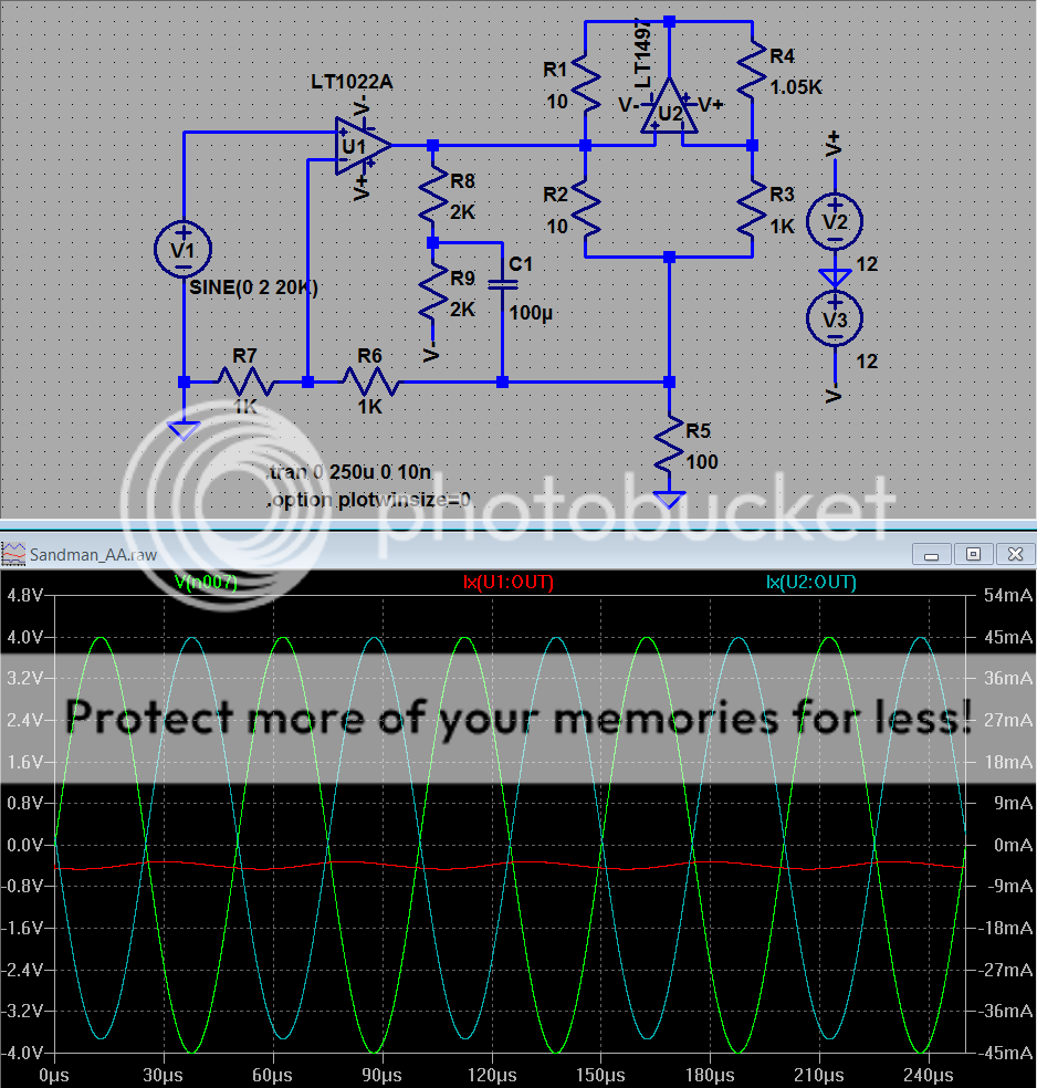
I trimmed the gain of the current buffer for mostly quadrature error current in U1's output
I also show Class A bias of U1 with bootstrap ccs R8,9, C1
I believe better perfromance can be had with faster, higher current buffer chip U2 fully nested inside the feedback loop of U1 in a Jung style multiloop
U2 buffer should be a different chip to eliminate thermal feedback, faster than U1 to avoid destabilizing the loop and most obviously - higher output current - a cfa op amp as shown meets these criteria but requires good layout, bypassing to work well
it also helps to check that U2 input common mode range exceeds the required output V swing
I trimmed the gain of the current buffer for mostly quadrature error current in U1's output
I also show Class A bias of U1 with bootstrap ccs R8,9, C1
I believe better perfromance can be had with faster, higher current buffer chip U2 fully nested inside the feedback loop of U1 in a Jung style multiloop
Attachments
Last edited:
U2 supplies almost all of the load current - compare the U1:OUT current to U2:OUT in the plot (red, blue trace: right axis for current)
(U2 supplies ~40 mA into the 100 Ohm load plus some more for feedback networks and ccs)
unloading the output of U1 should reduce thermal and gain errors
some people like to claim the U2 amp isn't "in the signal path" so the improvement supposedly doesn't add as much "feedback artifact"
Jung's multiloop amps can give much better performance with the same components but input amp and buffer are in series and you have very large loop gain in the signal path
Last edited:
oops, out of edit time...
U2, R1,3,4 form a vccs which senses the drop across R2 and supplies a near equal amount of current into the U1:OUT node
(the op amp subcircuit current direction is positive into the op amp so the displayed current traces are inverted relative to R5 load current)
if the cancelation is accurate enough the current demand on U1:OUT can be low enough for Class A bias of U1 output to be practical as shown - further reducing error in the U1 amp
for a demonstration of U2 function you can remove R1 (or edit its value to 10g, g=GigaOhm) and you should see the output clip as U1 current limits trying to drive 100 Ohm load R5 without the aid of U2
Last edited:
Jung's multiloop amps can give much better performance with the same components but input amp and buffer are in series and you have very large loop gain in the signal path
Interesting! I built a META42 using AD8066 and EL2001 buffer, this uses the Jung multiloop idea. It sounded pretty bland to me, maybe I should rig it up again to compare to the classAA board? I reckon I prefer the classAA circuit (although it's a few years since I listened to the META). Maybe it was the poor pcb layout (poor grounding and decoupling) that limited the META and not the topology?
Hi There,
I recently purchased this board not because it was class AA but because I wanted to build a versatile dual buffer amp using OPAMPs. This one is already soldered, there are 2 opamps per channel, so I was going to put a volume between NE5532 and NE5534 circuit so that it act as a high impedance input and low impedance output buffer with minimal effect from volume. I was going to short or remove some resistors to make this circuit a buffer.
But anyway, I got curious about the circuit and saw this thread. I attached the circuit since someone said he couldn't see it.
I understand principles of opamp but I have no experience in practically using opamps for audio. I have a few questions.
1. Would I need input or output caps? I saw a few circuits that use caps, also a few circuits that don't.
2. If I remove R3 of NE5534 (R8 of 5532), and then short R4 of 5534 (R12 of 5532), then their gain will be unity. Is this correct?
3. What will be the result if I use 15V rail?
4. Will the second half of 5532 still be OK to be left there for buffer?
Thanks,
Doug
Attachments
Caps on the input and output are a good idea generally. A circuit such as this has a response down to DC. That means if the source has a DC offset, then that offset will be amplified by the gain of the circuit. A cap on the input prevents that. A cap on the output prevents DC offset from the circuit itself appearing at the output. The slightest DC across a volume control will make the action "crackly" as it is rotated. The 5534/2 are very poor as regards low DC offsets, to get around that you need either a FET opamp or a more modern device with much lower input bias currents.
The resistors will do as you describe but there may be stability issues with the 5534 unless it is compensated correctly for unity gain.
Supplies can be anywhere between the chosen devices recommended limits.
Second half of 5532 can be used for whatever you want... it's independent.
The resistors will do as you describe but there may be stability issues with the 5534 unless it is compensated correctly for unity gain.
Supplies can be anywhere between the chosen devices recommended limits.
Second half of 5532 can be used for whatever you want... it's independent.
Thanks a lot for the answers.
I would add caps for 5534 input. Any suggestions: cap value, model, etc? And do I still need input resistor when I use input caps? As I understand, the input resistor is to restrict any dc current so it won't be needed for Ac coupling. I might be wrong though.
I would add caps for 5534 input. Any suggestions: cap value, model, etc? And do I still need input resistor when I use input caps? As I understand, the input resistor is to restrict any dc current so it won't be needed for Ac coupling. I might be wrong though.
You would just add a cap in series with R1 or R7. The value depends on the lower cut off frequency you desire. Fig 1 here.
High-pass filter - Wikipedia, the free encyclopedia
You woudn't normally need R1 or R7 or the 100pf caps. These resistors have no practical effect on input currents but could be used to configure a passive filter with the 100pf cap.
Unless you need an HF filter like that to address a specific issue or part of the design then I would suggest omitting it.
There are a lot of subtleties to a circuit like this. The opamp DC input currents have to be kept equal for minimum DC offset. That means the DC path on - and + inputs has to be the same resistance to achieve that. Use a FET opamp and that problem disappears. You could a TL072 and TL071 as direct swaps for these.
Also see,
http://www.diyaudio.com/forums/anal...u-have-checked-see-its-stable-havent-you.html
The circuit works fine fully dc coupled. The 5534 has offset trimmig and the 5532 section seems to have lowish dc offset (obviously depends on the individual opamp). All the circuit impedances are reasonably low.
It is important to change the elec caps to something reasonable e.g. Pana FA etc. The Suscons fitted to the board can only loosely be described as capacitors.
I wonder what is would sound like with LM4562s?
It is important to change the elec caps to something reasonable e.g. Pana FA etc. The Suscons fitted to the board can only loosely be described as capacitors.
I wonder what is would sound like with LM4562s?
Mooly,
In my country, mooly means physics, I appreciate your mooly answers.
Thank you,
Doug
You're welcome
I found new Ebay item using this class AA (they claim). It says:"
Panasonic AA class line is a voltage controlled amplifier and current drive amplifier constitute a bridge, the voltage controlled amplifier in the equivalent to no-load status (i.e. the output current is zero), even if connected to a heavy load, even if it is not the same as the voltage and current waveforms of complex dynamic impedance, the voltage controlled amplifier can still work in the CPI state, because of its excellent performance and near-perfect sound performance and loved by the people."
Anyone understand what is claimed?
Ebay Class AA new description
- Status
- This old topic is closed. If you want to reopen this topic, contact a moderator using the "Report Post" button.
- Home
- Source & Line
- Analog Line Level
- Class AA Opamp Schematic