Hello Doug,
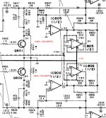
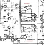
I attached two Class-AA schematics from Technics famous CD-Player SL-PG700 and SL-PG900 which use Class-AA realized with OP-Amp as output driver/stage.
I do not fully understand the second OP-Amp now too. My hope is that you can compare original Technics schematics with something you would like to buy or build.
Best regards
Karsten
Attachments
Hello Doug,
I attached two Class-AA schematics from Technics famous CD-Player SL-PG700 and SL-PG900 which use Class-AA realized with OP-Amp as output driver/stage.
I do not fully understand the second OP-Amp now too. My hope is that you can compare original Technics schematics with something you would like to buy or build.
Best regards
Karsten
Thanks, Karsten.
I am very curious what the second op amp does.
Doug
Hello Doug,
I´m interested how the second OpAmp is working and where to fine Class-A in OpAmp solutions too. I´m sure, that Technisc do not include any "sensless" parts in his products because they will increase cost")
I try to simulate the original Class-AA schematic I provided to you, striping the premephasis build with C817,C819 and R845 in SL-PG700 left channel. Well, I´m far away from expert in LTSpice but I see no difference with/without second OpAmp.
We read some post before in this thread, that the second OpAmp will work as a high impedance for the first OpAmp and that all current will be thrown by the second OpAmp. Well this seemed a to simple description for me. Using a OpAmp with more possible current at output will do the job.
Mainly I wonder where to find a typical Class-A in this schematic. And what are the exact benefit of a Class-AA.
Personally I do not beleve that this will be only a marketing gag...
My hope is, that someone with more knowledge will read this therad and can provide us more light in the darkness of Class-AA
best regards
Karsten
I´m interested how the second OpAmp is working and where to fine Class-A in OpAmp solutions too. I´m sure, that Technisc do not include any "sensless" parts in his products because they will increase cost
I try to simulate the original Class-AA schematic I provided to you, striping the premephasis build with C817,C819 and R845 in SL-PG700 left channel. Well, I´m far away from expert in LTSpice but I see no difference with/without second OpAmp.
We read some post before in this thread, that the second OpAmp will work as a high impedance for the first OpAmp and that all current will be thrown by the second OpAmp. Well this seemed a to simple description for me. Using a OpAmp with more possible current at output will do the job.
Mainly I wonder where to find a typical Class-A in this schematic. And what are the exact benefit of a Class-AA.
Personally I do not beleve that this will be only a marketing gag...
My hope is, that someone with more knowledge will read this therad and can provide us more light in the darkness of Class-AA
best regards
Karsten
Attachments
Hey Mooly,
Well I´m a beliver in the good part of the mankind. To implement some obscure schematic with no effect in the complete product line make no sense for me. The risc is to high if someone will check this andyou will lost reputation ( See Automotive VW... )
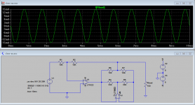
Nevertheless, I checked the current on Rload which is alltime the same ( +/- 15mA ) independent if the second OpAmp is connected or not. For that there must be an other benefit instead simple more output current.
In normal case there should be a patent hold by Technics/Matsushita concerning this special schematic. And if we can find it, we know exactly what´s going on here. In your Post #4 you wrote something about "Aubrey Sandmans Class S". This may a hint to get more information. JCX did an analysis post #7,9 and 10 of a similar schematic but not the same which I found within an original Technics service manual.
best regards
Karsten
Some Post earlier there
Well I´m a beliver in the good part of the mankind
. To implement some obscure schematic with no effect in the complete product line make no sense for me. The risc is to high if someone will check this andyou will lost reputation ( See Automotive VW... )Nevertheless, I checked the current on Rload which is alltime the same ( +/- 15mA ) independent if the second OpAmp is connected or not. For that there must be an other benefit instead simple more output current.
In normal case there should be a patent hold by Technics/Matsushita concerning this special schematic. And if we can find it, we know exactly what´s going on here. In your Post #4 you wrote something about "Aubrey Sandmans Class S". This may a hint to get more information. JCX did an analysis post #7,9 and 10 of a similar schematic but not the same which I found within an original Technics service manual.
best regards
Karsten
Some Post earlier there
Attachments
What I can't understand is this... each opamp is of the same type, its not like one is a super high quality device (but say lacking drive ability). I can't really see what is being achieved here.
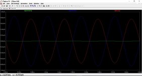
Your load of 100 ohms causes both opamps to deliver a distorted current waveform. Increase that load to say 2k and the first opamps contribution falls to a couple of microamps. Now it start to make more sense... almost.
The first opamp is essentially filling in the area around the crossover region. The resistor network forms a bridge, the second opamp is more of a comparator. The result is that the first opamp sees a near infinite load impedance.
I remain to be convinced.
Attachments
Mooly,
Thanks a lot for your investigation. I simple copy the 100 Ohm load from Post#7 to see if there is a significant change removing U2 because it was sayed that U2 will do the current job.
I see, I have to go more deep in this little riddle.
In meantime I found interesting information just in this Forum:
http://www.diyaudio.com/forums/solid-state/32254-new-class-whats-mean.html
See Post # 2 and Post # 19..
Nice task to dig out this old story about Class-AA. I did lot´s of repair working in end of 80´s in a RF Studio. We where specialised for Technics, Panasonic, Toshiba and so on.. In fact: Technics devices are my secret love...
Regards
Karsten
Interesting, thanks for that
I honestly remain to be convinced when this applied to opamps though. The idea makes more sense when applied to a power amp although I recall Sandman never showed an working example for very low impedances (such as a speaker). Wish I still had all the old Wireless Worlds now, I remember the Sandman debate rumbling on.
I honestly remain to be convinced when this applied to opamps though. The idea makes more sense when applied to a power amp although I recall Sandman never showed an working example for very low impedances (such as a speaker). Wish I still had all the old Wireless Worlds now, I remember the Sandman debate rumbling on.
Hello,
Found interesting article here but unfortunately in russian. I know someone who is a russian native speaker. May take a while but there is hope. I love puzzles
?????? ????? 5 ????? 1998 ???. ?? ???????
Take a look to the pictures. It´s an eye opener for me by simply using a different arrangement of the schematic. U1 is a typical Class A and U2 a Class B and both OpAmps working to a Resistor bridge.. fine..
Regards
Karsten
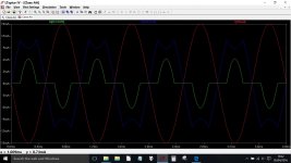
Look at U1's output current in AC analysis.It is proportional to U2's loopgain and at the end the current exceed load current.The excess current flows to U2 output because, around/after U2's gain crossover frequency, U2 output voltage go to 0V. This is one of the con in class AA and class S , the resistor U1 output to U2 output become U1's load after U2 cutoff. Another con is output impedance without global loop feedback (Class AA is the Class S with global loop feedback).
The Pro is bandwidth. Even if U2 go cutoff, output voltage do not cutoff but some amount of attenuation with phase delay-lead-factor.When you use low fT power transistor in U2's output stage, the gain crossover frequency is limited by the transistor. But global loop feedback (of class AA) can exceed the transistor's fT.
The Pro is bandwidth. Even if U2 go cutoff, output voltage do not cutoff but some amount of attenuation with phase delay-lead-factor.When you use low fT power transistor in U2's output stage, the gain crossover frequency is limited by the transistor. But global loop feedback (of class AA) can exceed the transistor's fT.
- Status
- This old topic is closed. If you want to reopen this topic, contact a moderator using the "Report Post" button.
- Home
- Source & Line
- Analog Line Level
- Class AA Opamp Schematic