How many volts voltage support?
Can AC28*2?
voltage AC 30*2
DC < + - 45V
welcome send me an emial if you have any questions .
ljm_ljm@126.com
")
Thanks for your help very very much!
I'll buy it.
I have a "Taobao.com" account.Can I buy it on "Taobao.com"?
Please E-Mail to me 'Taobao' Links for your amp 'MX50' Version 6.0
Thank you.
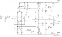
it s seems there s a flaw in the voltage amplifier 's current generator....
it must be biaised separately, and not using the current generator of
the differential stage...
connect R6 to ground and give it a value of 15K, and connect two serial
diode between the base of Q4 to positive supply...the current will be about
6 mA through this transistor..
Q4 and Q12 are not correctly rated, they won t stand the power..
use BD139/140 instead, and you can use these transistor to replace
Q5 and Q9 , it will be better than the plastic used BC639/640....
the output stage is a compound pair, and it is more prone to
oscillations than a emitter follower configuration, not mentionning
that the latter has better distorsion at low level and is easier
to stabilize...
for the rest, this schematic should sound fine...
wahab;1995640the output stage is a compound pair said:I have usually found with the drivers that you need 100pf-ish from the collectors to the bases. If it needs it then it will show up as oscilation on the output.
well, i didn t experiment with such compensation capacitors,
as i found somewhat curious to make the slowest stage of an
amp even more slow...
i think the problem of the coumpound is that the emmiter of
the driver is connected to the load, making it subject to
reverse voltages from the speaker...a cure that is not one is
to add resistors to the driver s emitters...unfortunatly, this
make the complete stage perform poorly...
despite the claim by many that the coumpound is better than
the emitter follower pair, i m somwhat pessimistic about it, and
i prefer the latter...i used darlington countelessly, preferably from
sanken which product some with outstanding performances,
and yes, they are not ridiculous..my prefered are the
MP1620/MN2488 complemantary pairs,
150V/150W/10A/55MHZ/ 100pF Cbc/HFE 5000 mini..
why ask for more?...
Banned
Joined 2002
well, i didn t experiment with such compensation capacitors,
as i found somewhat curious to make the slowest stage of an
amp even more slow...
i think the problem of the coumpound is that the emmiter of
the driver is connected to the load, making it subject to
reverse voltages from the speaker...a cure that is not one is
to add resistors to the driver s emitters...unfortunatly, this
make the complete stage perform poorly...
despite the claim by many that the coumpound is better than
the emitter follower pair, i m somwhat pessimistic about it, and
i prefer the latter...i used darlington countelessly, preferably from
sanken which product some with outstanding performances,
and yes, they are not ridiculous..my prefered are the
MP1620/MN2488 complemantary pairs,
150V/150W/10A/55MHZ/ 100pF Cbc/HFE 5000 mini..
why ask for more?...
They sometimes put Baxandall diodes across the driver emitter resistors.
I found in this case that I definitely needed the extra capacitors.
The Baxandall diode turns a phase splitter into a amplifying stage.
[They sometimes put Baxandall diodes across the driver emitter resistors.
I found in this case that I definitely needed the extra capacitors.
The Baxandall diode turns a phase splitter into a amplifying stage. ]
you mean those diodes used in the pnp driver emitter of a
bottom side of a quasi complementary pair ?...
well, from the start i found the thing tricky..
at the time, pnp power bjt were expensive, but i did found
a pair that was much better than the usual 2N3055 and its likes...
BDW51C/52C if my memory is good..
in fact i almost never used a compound pair.
and i rarely see an amp using it, unless it s a ESP design, as
rod elliott is a supporter of such a stage...
[/what's the price of these little guys ]
about the sankens?...i did bought them from a retail shop that was
clearing its stocks, at 4 euros /piece
here the datasheet : MP1620 Datasheet pdf - Transistor De Puissance De Silicium De Type De Moule - Sanken
it s seems there s a flaw in the voltage amplifier 's current generator....
it must be biaised separately, and not using the current generator of
the differential stage...
connect R6 to ground and give it a value of 15K, and connect two serial
diode between the base of Q4 to positive supply...the current will be about
6 mA through this transistor..
Q4 and Q12 are not correctly rated, they won t stand the power..
use BD139/140 instead, and you can use these transistor to replace
Q5 and Q9 , it will be better than the plastic used BC639/640....
the output stage is a compound pair, and it is more prone to
oscillations than a emitter follower configuration, not mentionning
that the latter has better distorsion at low level and is easier
to stabilize...
for the rest, this schematic should sound fine...
Thanks for your help. I want to try it at next weekend.
Do you like this Amp?
Not to seem like a spoilsport, but this thread should really be over in the solid state forum.This is a big amp, and this forum is for little preamps....
thanks,i did not notice.
it s seems there s a flaw in the voltage amplifier 's current generator....
it must be biaised separately, and not using the current generator of
the differential stage...
connect R6 to ground and give it a value of 15K, and connect two serial
diode between the base of Q4 to positive supply...the current will be about
6 mA through this transistor..
Q4 and Q12 are not correctly rated, they won t stand the power..
use BD139/140 instead, and you can use these transistor to replace
Q5 and Q9 , it will be better than the plastic used BC639/640....
the output stage is a compound pair, and it is more prone to
oscillations than a emitter follower configuration, not mentionning
that the latter has better distorsion at low level and is easier
to stabilize...
for the rest, this schematic should sound fine...
thank you for your suggestion.
this amplifier voltage+ -35v
Q4 Q12 about current 6ma
POWER about 35*0.006=0.21 watt.< bC546 extreme power 0.6WATT.
moreover,BC546 have the lower COB and more HFE FT of TO126 transistor.
right,output stage prone to oscillation than emitter follower.stability of the actual running.
this output stage fewer crossover than emitter follower.
as the output stage with gain .need reduction feedback depth.
suggestion please.
well, i didn t experiment with such compensation capacitors,
as i found somewhat curious to make the slowest stage of an
amp even more slow...
i think the problem of the coumpound is that the emmiter of
the driver is connected to the load, making it subject to
reverse voltages from the speaker...a cure that is not one is
to add resistors to the driver s emitters...unfortunatly, this
make the complete stage perform poorly...
despite the claim by many that the coumpound is better than
the emitter follower pair, i m somwhat pessimistic about it, and
i prefer the latter...i used darlington countelessly, preferably from
sanken which product some with outstanding performances,
and yes, they are not ridiculous..my prefered are the
MP1620/MN2488 complemantary pairs,
150V/150W/10A/55MHZ/ 100pF Cbc/HFE 5000 mini..
why ask for more?...
yes. i very like this darlington ,i have used this dralington MF1620/MN2488 in my amplifier before.
but it is difficult to by sanken mp1620/mn2488 in china.so i had to make do and mend with drlington from sony amp.
perhaps don't sell MP1620 by retail ,SONY OEM.but i dont know this dralington
i don't know whether it can use to MX50.
this output used mp1620/2488 in my amp.
Attachments
- Status
- This old topic is closed. If you want to reopen this topic, contact a moderator using the "Report Post" button.
- Home
- Source & Line
- Analog Line Level
- 50watt class-b amp mx50v6