Alan, thank you sooo much for helping me. I really appreciate it. Here is my next questions:
1. The unit is upgraded by Mike Elliott himself. As I understand from the caps, he removed C55 and used a 1uf - 425V cap (in my former message I wrote 8uf - 425, but now I'm correcting it). What other changes were applied, I can not say. My knowledge of electronics is not enough for that. So, should I keep it or look for a 200uf - 400 V cap for C55 also? This choice will effect cap selection.
2. In this thread Anatech suggested that
Should I remove that cap?
3. Some people on this forum suggested me to remove the electrolytics with film caps. But a 200uf - 400V film cap is really huge. Should I insist on film cap? BTW, C55 cap is a 25mm D - 65mm L cap.
1. The unit is upgraded by Mike Elliott himself. As I understand from the caps, he removed C55 and used a 1uf - 425V cap (in my former message I wrote 8uf - 425, but now I'm correcting it). What other changes were applied, I can not say. My knowledge of electronics is not enough for that. So, should I keep it or look for a 200uf - 400 V cap for C55 also? This choice will effect cap selection.
2. In this thread Anatech suggested that
C52 (110uF/100V) and C53 (1uF/200V) are across the 5651 reference
valve. The Tungsol data sheet recommends a maximum shunt capacitance
of 0.02uF. So the caps here are a mere 5000x too big. The easiest fix is to
just remove C52.
Should I remove that cap?
3. Some people on this forum suggested me to remove the electrolytics with film caps. But a 200uf - 400V film cap is really huge. Should I insist on film cap? BTW, C55 cap is a 25mm D - 65mm L cap.
Alta Vista audio used BlackGate VKs or NHs in 150uf/350V at these positions. I have seen pics with the BG powertanks (200uf/200V) used here also. As Alan (vivavee) stated, 300V should be considered the minimum here.ln some photos of upgraded SA-5.1 units l see caps like 150uf - 350V and no 0.47uf's. What's the purpose of 0,47uf's?
I used the BG VK 150uf/350V here on mine, but didn't notice any difference really. The BGs supposedly had better HF performance than std. electrolytics such as the Spragues used originally, hence no bypassing. I paid around $15 or so each for the BGs. You can't find them now, other than ebay, which are a) really expensive, and b) possibly fake. I had done these mods in trying to duplicate what Mike was doing at AVA, and before I had gotten the wise counsel of Alan
")
Don't bother. These could be fakes, and they don't really make a difference. I'd fix the power supply problems in this preamp first. Check this thread (you've posted in it)
http://www.diyaudio.com/forums/tubes-valves/78298-counterpoint-sa-5-1-a-29.html
But, its your money.
http://www.diyaudio.com/forums/tubes-valves/78298-counterpoint-sa-5-1-a-29.html
But, its your money.
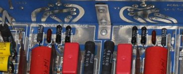
The big blue Sprague 1501s are electrolytic capacitors.
The white Wondercaps are film caps.
If you replace any of the power supply capacitors, you need to choose capacitors with a voltage rating greater than 260V, preferably greater than 300V to give you a safety margin. The original capacitors in this unit run at or below their rated voltage which is not best practice
Alan sums it up pretty well, had you read it...
Plus the original caps are what, 25+ years old?
I dont get it
those blue Sprague could be the best of the best
and why say they are under rated and should be changed ?
the are working now, and doing fine, right ?
and have done so for a while ?
so what is the problem ?
Are you seriously recommending running 200V capacitors at 260V?
There is NO recommendation to change the caps - Firochromis is asking whether he should or not.
There is the strong recommendation that IF a change is made then a capacitor with adequate voltage rating should be chosen.
I dont get it
those blue Sprague could be the best of the best
and why say they are under rated and should be changed ?
the are working now, and doing fine, right ?
and have done so for a while ?
so what is the problem ?
Hi, maybe I should explain my motivation earlier. I wrote a few times on my posts, and even if hadn't everybody already realized now that I don't have abilities to mod an electronic unit. This equipment, which I'm really really enjoying is nearly as old as me, and I'm listening it everyday. If an error occurs and I can not hear that music:
- find which equipment on my system caused that,
- find what happened,
- find the fix for it on forums,
- order the needed part and wait it to it arrive from other side of the world,
- find a technician to fix it
- see if there are more components effected on the previous failure
- find solution for them also....
I tell you, it will take a month or two, at the minimum. My first reason is to re-new the only unchanged parts of my amplifier.
Secondly, there are measurable reasons to make this change: People I trust, who have the ability I lack, says some caps has more voltage on them than they are rated for.
Thirdly, there are some un-measurable reasons for me. While Mike designing this amplifier, he were ordering the parts most likely by post, I mean by writing mails...with stamps on them. Now the world have mobiles, internet etc. I tend to believe that there *may* be some improvements on the audio components...
So, since this forum is more technique related than other forums, I'm looking for a solution here and not on Agon or Asylum. Other forums probably should more interested on my third reason, I listed above. Then the conversation would turn into a brand war. No, I'm trying to give life to my amplifier to live as long as me. But still, I need recommendations to use which parts
C50: This one has a strange shape than others. A regular shaped film cap like, AuriCap XO 1uf - 600V is ok to use?
C51: I can fit an Auricap XO 10uf - 400V here. Is it good to have a film cap at this position? A smaller electrolytic at this position leaves more space for C55/C57/C58 choices. Though, Jensen's I listed below fits in with AuriCap.
C52: Earlier on this topic, it was advised to move this cap. Should I do that? Otherwise Jensen Axial electrolytic seems fine to me.
C55: This cap was removed by Mike Elliott. I don't know if my regular technician can find how Mike compensated this. So, do you think I should leave it as it is or use a proper 150uf-350V here?
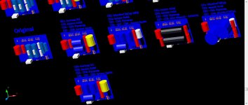
C57/C58: I can not fit film caps here, so electrolytics seems the only option (Look to the image attached, the last one to the right has Mundorf MCaps, I have to cut the upper plate). Jensen Axial or Jensen 4pole is ok? BTW, they are around $60 also. So if I can find a trustable source for Black Gates VK's, should I opt for them (because I guess I found one yesterday)?
C77: I understand that this one must be 47uf-500V. Any suggestion, since I can not locate an exact 47uf-500V on parts connexion, and hesitate to buy a no-name unit from ebay?
C78: This one will 100uf-500V. Need suggestion for that one also.
My unit was rewired for [FONT=Georgia, Times New Roman, Times, serif][SIZE=-1]6BW4 at the earlier owner and I guess that [/SIZE][/FONT]after rewire he chose 6BW4 tubes (there no markings on the tube). I learned from this topic that 6CA4 would be better to use. Any recommendation for that tube, Siemens, GE others?
Attachments
Last edited:
There is NO recommendation to change the caps
There is the strong recommendation that IF a change is made then a capacitor with adequate voltage rating should be chosen.
ok
Plus the original caps are what, 25+ years old?
and thats where I'm getting confused ...its contradictingAre you seriously recommending running 200V capacitors at 260V?
no Im not recommending anything other than he should keep his fingers away from it
if its perfectly stable in a lab test, and not noisy, humming or showing any kind of strange behaviour, then I would say everything is tip top...or what ?
Yes, it is fineHi, maybe I should explain my motivation earlier. I wrote a few times on my posts, and even if hadn't everybody already realized now that I don't have abilities to mod an electronic unit. This equipment, which I'm really really enjoying is nearly as old as me, and I'm listening it everyday. If an error occurs and I can not hear that music:
- find which equipment on my system caused that,
- find what happened,
- find the fix for it on forums,
- order the needed part and wait it to it arrive from other side of the world,
- find a technician to fix it
- see if there are more components effected on the previous failure
- find solution for them also....
I tell you, it will take a month or two, at the minimum. My first reason is to re-new the only unchanged parts of my amplifier.
Secondly, there are measurable reasons to make this change: People I trust, who have the ability I lack, says some caps has more voltage on them than they are rated for.
Thirdly, there are some un-measurable reasons for me. While Mike designing this amplifier, he were ordering the parts most likely by post, I mean by writing mails...with stamps on them. Now the world have mobiles, internet etc. I tend to believe that there *may* be some improvements on the audio components...
So, since this forum is more technique related than other forums, I'm looking for a solution here and not on Agon or Asylum. Other forums probably should more interested on my third reason, I listed above. Then the conversation would turn into a brand war. No, I'm trying to give life to my amplifier to live as long as me. But still, I need recommendations to use which parts
C50: This one has a strange shape than others. A regular shaped film cap like, AuriCap XO 1uf - 600V is ok to use?
This is what I used here. Near perfect fit.C51: I can fit an Auricap XO 10uf - 400V here. Is it good to have a film cap at this position? A smaller electrolytic at this position leaves more space for C55/C57/C58 choices. Though, Jensen's I listed below fits in with AuriCap.
C52: Earlier on this topic, it was advised to move this cap. Should I do that? Otherwise Jensen Axial electrolytic seems fine to me.
Both Chris (Anatek) and Alan (vivavee) were Counterpoint field service, etc. for their particular countries/regions. They both know what they are talking about, and know tube gear and design. If they say to remove it, I would.
Not sure why C55 would have been removed. Axial electrolytics are becoming hard to find. As you mentioned, film caps are quite large and impossible to fit into the form factor of this preamp. Mike used Cerafines or Black Gates and charged accordingly for his "upgrades". If you feel the need to change these, put something in that physically fits, meets the appropriate voltage rating (300Vdc or higher). If you have to use radial caps and wire them in, then fine (which was what Mike did with his). I used a pair of 220/220uf 350V Cerafines in mine for awhile. Their large physical size actually induced noise into the volume pot, so don't do something like that. Something like the Panasonic TS-Hx series might work nicely.C55: This cap was removed by Mike Elliott. I don't know if my regular technician can find how Mike compensated this. So, do you think I should leave it as it is or use a proper 150uf-350V here?
C57/C58: I can not fit film caps here, so electrolytics seems the only option (Look to the image attached, the last one to the right has Mundorf MCaps, I have to cut the upper plate). Jensen Axial or Jensen 4pole is ok? BTW, they are around $60 also. So if I can find a trustable source for Black Gates VK's, should I opt for them (because I guess I found one yesterday)?
I would suggest something like Panasonic TSU or TSUP if you can find them. I got some from Digikey (100uf/500V), but they don't seem to carry them anymore. Here is what a quick search turned up:C77: I understand that this one must be 47uf-500V. Any suggestion, since I can not locate an exact 47uf-500V on parts connexion, and hesitate to buy a no-name unit from ebay?
C78: This one will 100uf-500V. Need suggestion for that one also.
Digikey
Bonus in that some of these are 105C temp rated. I would only change these out if the ones that are in there don't meet the proper specs. Yours is the one with paralleled(?) caps (4) in it? See what they are and how they are wired in (or have your tech do it).
Any good quality 6CA4 will be fine.My unit was rewired for [FONT=Georgia, Times New Roman, Times, serif][SIZE=-1]6BW4 at the earlier owner and I guess that [/SIZE][/FONT]after rewire he chose 6BW4 tubes (there no markings on the tube). I learned from this topic that 6CA4 would be better to use. Any recommendation for that tube, Siemens, GE others?
I am going to bow out of this thread now, and let VivaVee reply if he chooses to. I am not advocating replacing anything, but responding to your questions as you seem to want to make some changes. These changes would have been done by Mike as part of his power supply "upgrades".
Last edited:
Thank you Pars for your excellent and clear help...
Thanks others for their contribution as well. To fix the problems I searched 150uf-200uf / 350-400v electrolytic caps for C55/C57/C58. Digikey give me some unknown-to-me Nichicon's and CDE's. I really get tired of searching them each.. Partconnexion has Jensen's around $40-70. So I decided to buy Black Gate VK's from a trustable source. PM me if you want to learn the source. I paid slightly higher than the Jensen's but considering that BG was Elliott's top choice I'm happy with this decision. I know some of you don't like Black Gate's but I'm get tired of searching the things I don't understand. It is better to give an end to this.
Thanks others for their contribution as well. To fix the problems I searched 150uf-200uf / 350-400v electrolytic caps for C55/C57/C58. Digikey give me some unknown-to-me Nichicon's and CDE's. I really get tired of searching them each.. Partconnexion has Jensen's around $40-70. So I decided to buy Black Gate VK's from a trustable source. PM me if you want to learn the source. I paid slightly higher than the Jensen's but considering that BG was Elliott's top choice I'm happy with this decision. I know some of you don't like Black Gate's but I'm get tired of searching the things I don't understand. It is better to give an end to this.
On the rear of the vertical PCB, between V5 and V6. It is a 22R 2W resistor.Can anybody tell me where is the resistor #64 located in chassis?
Hi all,
Thank you Alan for your help. It make me clear the position of the resistor but it is still absent and luckily Pars helped me with that.
Thank you Alan for your help. It make me clear the position of the resistor but it is still absent and luckily Pars helped me with that.
Now, while I was studying the resistors on the line stage I noticed that ME has changed them to different value ones. According to schematics, R30 should be 681R; R19 and R18 should be 51R; R20 should be 10K but on my board they are 49.9R and 100R and 49.9K respectively. He also changed the R5 and R10 of the phono stage from 47K/27K to 49.9K both. Again an inaccurate schematics?Remember that I told you Mike's schematics may not be accurate. The resistor you ask about is a relic from the SA5 and will not be in your unit. The SA5 used heaters that were wired in pairs in series with a 12V heater supply. Per the service manual detailing changes to the SA5.1:
Tube filaments re-wired to parallel operation. This change is designed
to make certain that each tube sees exactly the right filament voltage
(6 volts). The previous version (12 volt) did not assure exact voltages
for each tube, due to filament resistance variations.
Attachments
reminds me of once I asked a known skilled EE to help me adjust my amp
he said yes, and started looking at it
suddenly he was very silent and did nothing for some minutes
just looking at something
then he changed a few resitors
it looked a bit weird and somewhat messy
the funny thing, he only did it with one channel
I got home and it now sounded very different
I found a it bit too soft, and removed his mod, and remounted original resitors
when he later noticed I had changed his 'adjustment' he got very angry
he would never work for me again
and I still wonder what it was he had adjusted
According to schematics, R30 should be 681R; R19 and R18 should be 51R; R20 should be 10K but on my board they are 49.9R and 100R and 49.9K respectively. He also changed the R5 and R10 of the phono stage from 47K/27K to 49.9K both. Again an inaccurate schematics?
The schematic is correct in the sense that that is what values the SA5 was shipped with originally. The changes, if made by Mike Elliott, presumably reflect his latest thinking
R30 is the line stage valve grid stopper. Changing from 681 to 49 would theoretically lower the noise (not sure about the significance of that) but is otherwise benign.
R18/19 are the line stage current sharing resistors. The change will improve current sharing so the change is benign.
R20 is the line stage plate load. Changing from 20k to 49k is significant. The line stage gain will increase proportionally but the change in R18/19 may compensate for this.
R5/R10 are the phono stage plate loads. The R5 change seems insiginificant but R10 will increase second stge gain in the phono stage and increase the phono stage output impedance
Not sure if that helps at all.
could the gain changes have been done to better suit a high output MC pickup, instead of MM pickup ?
or someone have been driving a medio/normal output MC pickup directly without further MC preamp ?
(would be perfectly possible with sensitive speakers)
Probably... With my 5mV cartridge the volume pod is normally around 7 - 8 o'clock level.
- Status
- This old topic is closed. If you want to reopen this topic, contact a moderator using the "Report Post" button.
- Home
- Source & Line
- Analog Line Level
- Counterpoint SA5 Preamp Problem