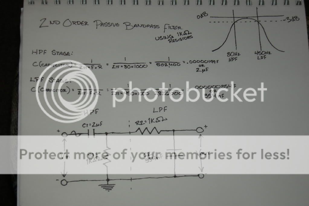
I am looking to create my first project. I would like to design a bandpass filter to run a pair of 10in slim subs to act as mid-bass drivers for my system. My intent is to run an 80hz HPF which goes into a 450hz LPF to create a usable BPF. Now from some of my readings, low frequency passive filters often have issue due to impedance irregularities.
http://sound.westhost.com/lr-passive.htm#s3.1.1
Often times the Impedance correction Zobel network is implemented to compensate for the rising impedance issues. However these sorts of x-overs lend themselves to power dissipation and furthermore a reduction in efficiency.
Now the other alternative is to go to an active filter. In which case, I would be inclined to go with a Multiple Feedback Bandpass Filter.
http://www.ecircuitcenter.com/Circuits/MFB_bandpass/MFB_bandpass.htm
This sounds solid enough, however the passive filter seems much simpler, but if the performance of the passive filter will be so much worse than the active filter than I suppose I'll just suck it up and make it. I'm looking for the input of the fine people at DIYaudio.com, if they're willing")
Before I was enlightened (maybe I just made things more complicated instead) I concocted a simple and I'm sure very wrong 2nd-order passive bandpass filter.
Any thoughts?
http://sound.westhost.com/lr-passive.htm#s3.1.1
Often times the Impedance correction Zobel network is implemented to compensate for the rising impedance issues. However these sorts of x-overs lend themselves to power dissipation and furthermore a reduction in efficiency.
Now the other alternative is to go to an active filter. In which case, I would be inclined to go with a Multiple Feedback Bandpass Filter.
http://www.ecircuitcenter.com/Circuits/MFB_bandpass/MFB_bandpass.htm
This sounds solid enough, however the passive filter seems much simpler, but if the performance of the passive filter will be so much worse than the active filter than I suppose I'll just suck it up and make it. I'm looking for the input of the fine people at DIYaudio.com, if they're willing
Before I was enlightened (maybe I just made things more complicated instead) I concocted a simple and I'm sure very wrong 2nd-order passive bandpass filter.
Any thoughts?
So i need to find out what the output impedance of my 5-band parametric EQ is and find out what the input impedance of the amplifier. So then I merely meter the RCA output and inputs respectively in relation to the amp or EQ ground?
And please excuse the ignorance, but the passive line level filter is what in regards to the inner limits?
And please excuse the ignorance, but the passive line level filter is what in regards to the inner limits?
a resistor + capacitor is a first order filter.
You need to add an inductor for each half of the passive filter to achieve second order roll off.
Simply cascading two first order (Butterworth) filters will give approximately Q=0.5 and both filters will be affected by the non zero and non infinite loading that you have become aware of.
That's you now up to 4inductors and 4capaictors for your two channel second order passive filters.
Now each filter will be affected by the changing impedance of the load.
You should look at compensating the passive filter to take account of the VC reactance that cannot be avoided. Adding a Zobel to partially correct for the rising impedance with frequency is a common compensation.
That is another pair of capacitors. This is starting to get expensive with the number of alternatives that will be needed to arrive at the intended roll off slopes and frequencies, first guess will not be right, even third guess resulting from measurements of the actual working filter is likely to be wrong.
Product development is not cheap, neither in material resources nor in the designer'stime.
Last edited:
- Status
- This old topic is closed. If you want to reopen this topic, contact a moderator using the "Report Post" button.