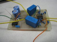
I would've laid it out nicer but I wasn't planning on using a virtual ground in the beginning.
The big caps are Rubycon 50V 220uF, paralleled. The small medium-blue ceramic caps in the middle are 50V 0.47uF, also paralleled.
The big caps are Rubycon 50V 220uF, paralleled. The small medium-blue ceramic caps in the middle are 50V 0.47uF, also paralleled.
Attachments
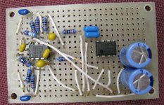
Only thing I can't work out is why there's 4 of those yellow film caps? I can only see a place for two, one from the opamps V+ to vGnd, and one from the opamps V- to vGnd. What are the other two connected to?
Actually, they don't look like film caps, either, they look like tants to me, which the definately shouldn't be.
The input caps (2.2uF on the schematic), which I'm assuming are the blue caps in the top and bottom left corners, shouldn't be tants either, they're really the worst cap for this particular job, they should be at least polyester box caps (though they're shown with polarisation markings, if you use them with an unpolarised cap it doesn't matter), and preferably polypropylene.
Those are the ceramic output caps, not the input caps. Why are tants bad as input caps? And, if I really should replace the tants with poly caps, do I still need to reach 2.2 uF?TheSeekerr [/i][B] Only thing I can't work out is why there's 4 of those yellow film caps? I can only see a place for two said:The input caps (2.2uF on the schematic), which I'm assuming are the blue caps in the top and bottom left corners, shouldn't be tants either, they're really the worst cap for this particular job, they should be at least polyester box caps (though they're shown with polarisation markings, if you use them with an unpolarised cap it doesn't matter), and preferably polypropylene.
Damn, I hooked it up and I didn't get any sound out of it. Would the WM-61a work with ~0.9V bias? For some reason a 9V battery hooked up only delivers ~0.951V, and yet the bias is ~0.9V. V+ doesn't get much at all. Also, the battery gets warm after a few minutes. It's a crappy no-name but I don't think that's normal.
So, it looks like I've hooked something up wrong, but the power supply was working correctly before I connected it to the preamp section. It would deliver +/- 1.6V from two AAs in series.
How would I go about diagnosing this? All the solder joints look good and there are no shorts. My best guess is that I might have overheated the ceramic output caps when I was trying to reposition them - possible? And then there's the thing with the power supply...
Definitely something weird going on, I'll have a closer look at it in the morning, right now I'm not thinking brilliantly.
Tants are fine for measurement preamps, but rubbish for recording preamps. And yes, the 2.2uF value is a minimum, it has been selected in order set the -3dB point of the low pass filter formed by it and the input impedance to a value < 20hz, I think it's about 9hz on that schematic.
Tants are fine for measurement preamps, but rubbish for recording preamps. And yes, the 2.2uF value is a minimum, it has been selected in order set the -3dB point of the low pass filter formed by it and the input impedance to a value < 20hz, I think it's about 9hz on that schematic.
Looks like I'd better pick up a pair of decent 9V batteries. The nominal minimum voltage for the TLE is 4V, while the op-amp needs at least +/- 2.5V.454Casull said:I disconnected the OPA from the power supply and tested the power supply with a Panasonic 1.5V battery which provided ~1.65V.
The positive rail is 0.9V while the negative rail is -.7V. Something's up...
EDIT: I found an unused 6V lantern battery putting out ~6.4V. The rails are +3.203V and -3.198V on my crappy RS multimeter, so I think the power supply works. Maybe the other side will work now too?
EDIT2: Nope. Is the op-amp output voltage supposed to be anywhere near the voltage of its rails?
Well, I built one of these tonight, just to follow along more closely with the discussion - mine is similar, except that itlacks all the power supply caps, except for 1.5uF across the rails to lower the impedance of the 9V battery supply.
It works fine - ie. the schematic is sound. You've made an error somewhere, the question is where.
Check that you've got the opamp pinout right. Check that you got the polarity of the power supply right.
The opamp output voltage will obviously be determined by the gain of the circuit and the input voltage. If there is no input voltage then no, the output voltage should be tiny, well below 100mV.
You should measure V+ and V- to be identical in magnitude, both before and after the rest is hooked up, ie with fresh 9V batteries, each rail to vGnd should measure right on 9V. I'm not sure what you should measure the bias across the mic capsule to be, since I've used different resistor values and only one 9V battery on my quick test version.
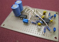
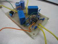
I'd consider rebuilding yours - it's a bit of a mess, and where there's mess, there's a risk of errors creeping in.
It works fine - ie. the schematic is sound. You've made an error somewhere, the question is where.
Check that you've got the opamp pinout right. Check that you got the polarity of the power supply right.
The opamp output voltage will obviously be determined by the gain of the circuit and the input voltage. If there is no input voltage then no, the output voltage should be tiny, well below 100mV.
You should measure V+ and V- to be identical in magnitude, both before and after the rest is hooked up, ie with fresh 9V batteries, each rail to vGnd should measure right on 9V. I'm not sure what you should measure the bias across the mic capsule to be, since I've used different resistor values and only one 9V battery on my quick test version.
I'd consider rebuilding yours - it's a bit of a mess, and where there's mess, there's a risk of errors creeping in.
I'll get around to rebuilding it when I pick up the two 2.2 uF poly caps.TheSeekerr said:Well, I built one of these tonight, just to follow along more closely with the discussion - mine is similar, except that itlacks all the power supply caps, except for 1.5uF across the rails to lower the impedance of the 9V battery supply.
It works fine - ie. the schematic is sound. You've made an error somewhere, the question is where.
Check that you've got the opamp pinout right. Check that you got the polarity of the power supply right.
The opamp output voltage will obviously be determined by the gain of the circuit and the input voltage. If there is no input voltage then no, the output voltage should be tiny, well below 100mV.
You should measure V+ and V- to be identical in magnitude, both before and after the rest is hooked up, ie with fresh 9V batteries, each rail to vGnd should measure right on 9V. I'm not sure what you should measure the bias across the mic capsule to be, since I've used different resistor values and only one 9V battery on my quick test version.
I'd consider rebuilding yours - it's a bit of a mess, and where there's mess, there's a risk of errors creeping in.
I'm measuring the output voltage right now with respect to the rails at +/- ~6.38V. It's the same as the rails, and the resistance betwen the output pins and the rails is high enough that my meter can't figure it out.
Is my chip toast?
Less harshness, less phase distortion (real phase distortion, that is - while there is a certain amount of minimum theoretical phase distortion, various designs add more, and tant's are not a good one for audio at all). Expect to hear the differences at the frequency extremes, not so much in the mids.
While I don't personally find all electrolytic caps to be unsuitable for audio, I do agree with the consensus that tants are rubbish for it.
While I don't personally find all electrolytic caps to be unsuitable for audio, I do agree with the consensus that tants are rubbish for it.
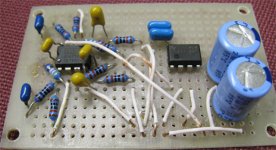
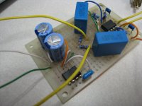
Alright, I got the damn thing working. Sort of. Pics to follow.
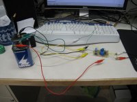
The output of the whole thing is quite low, even when plugged into the mic-in on my computer. I'm sending 6V to the cartridge right now. I'll try again when I get some decent 9V batteries, but could it make that much of a difference? Did I overheat the pre-amp inside the cartridge? Or, is there still something wrong with my circuit?
When I read the Vdc between the leads to the cartridge, it rises slowly and steadily from a very low number; I got impatient and stopped measuring after it went beyond 1.xxV. Could this have anything to do with it?
Attachments
- Status
- This old topic is closed. If you want to reopen this topic, contact a moderator using the "Report Post" button.
- Home
- Source & Line
- Analog Line Level
- Few questions about Linkwitz' mic amp circuit