Hi Slate,
This is a list right from FMTunerInfo.com for TU717 DIY Mods
As it turns out the two caps that you wanted to replace and the one cap I suggested are all three recommended here just in two different places. Sometimes two heads are better than one!
Sansui TU-517 and TU-717
Here's Jim again with Sansui TU-517 and TU-717 mods and tweaks:
First rule: Double-check, no, triple-check the polarity of all electrolytics and diodes when installing new ones. RCAs, IECs, coax connectors, cleaning this and that part are a given in most audio circles and need not be rehashed here. All differences between the TU-717 and TU-517, as far as these mods are concerned, will be noted. Starting with the power supply board marked F-2681, I usually change caps with good caps ranging from the stock value to three times as large. Also, be sure to use the stock voltage rating or higher when choosing new caps. I usually keep the same value or go as high as doubling the value of the power supply and decoupling caps. You can go from there per your expertise. Except for C25, I've not listed any caps below the value of 10 µF. Below is a list of parts I replace.
Power supply board #F-2681:
C03, C04: 470 µF 35V - Use the same brand and value in both positions.
C05: 100 µF 25V
C08: 100 µF 10V
C09: 10 µF 25V
C10: 47 µF 16V
Remember that the transistors, zeners and diodes "see" the heat when you change these caps, so good soldering practices need to be observed. I always change the rectifier diodes last in this step. Those are D01 and D02. As in the other mods, use Schottkys or the diode of your choice. Make sure they have a voltage rating of 100V or greater.
Decoupling caps to change around the boards are as follows:
Circuit Board #F-2678 - When reading the schematic left to right, top to bottom:
C24: 100 µF 16V
C34: 33 µF 10V
C50: 10 µF 10V
C82: 10 µF 16V
C100: 47 µF 16V
C101: 47 µF 6.3V
C74: 47 µF 16V
C73: 47 µF 16V
C72: 100 µF 16V
Circuit Board #F-2730 - The one under the metal case.
C18: 100 µF 16V
Circuit Board #F-2680 - The one directly behind the front level control. Be careful removing this little troublemaker. On the first TU-717, I took the entire tuner frame apart! Bob walked me through my second 717, and his method is much safer and easier. You must remove the faceplate, and remove the screws and nut that hold the board and volume control in place. Remove the wiring harness from the twists on the bottom. This gets those wires out of your way. Now lift the string off the small wheel closest to the back of the board to be removed. Then you barely, just barely, have enough room to pull the circuit board from its hole. Now you can replace with new caps. Remember, while it's out and dangling, there are quite a few coupling caps on that board to be replaced also.
C25: 3.3 µF 50V for the 717 and 6.8 µF 50V for the 517
C09 and C10: 33 µF 16V - I replace with the same value or leave alone. Use the same brand and value in both these positions.
C11 and C12: 470 µF 6.3V - Use the same brand and value in both these positions.
C23: 100 µF 16V
Circuit Board #F-2679 - No changes on the TU-517. Change these on the TU-717:
C05: 100 µF 16V
C03: 10 µF 16V
Audio path coupling caps to change around the boards are as follows:
Circuit Board #F-2730
C17: 47 µF 16V - Use the same µF value, audio grade.
C16: 10 µF 16V - Use the same µF value, audio grade.
Circuit Board #F-2678
C71: 3.3 µF 50V in the TU-717 - Replace with one 10 µF, audio grade.
C71 and C122: 4.7 µF 27V in the TU-517 - Replace C71 with one 10 µF, audio grade. Leave C122 blank. These were in parallel.
C75 and C76: 10 µF 25V - Change to 10 to 22 µF, audio grade, both the same.
Circuit Board #F-2680: The troublemaker.
C01 and C02: 1 µF Mylar? - Replace with good film caps (both the same) that will fit, or leave stock. Remember you have to stuff the bad boy back in place!
C13 and C14: 10 µF 25V - Replace with 10 to 22 µF, audio grade, both the same.
C19 and C20: 3.3 µF 10V - Replace with 4.7 to 10 µF, audio grade, both the same.
C21 and C22: 10 µF 25V - Replace with 10 to 22 µF, audio grade, both the same.
And that's it, except for the most important factor: a good alignment with good, matched filters. But that is another story for another page on the TIC. jim...
Maybe you can start with this for a basic Framework!
Hopefully if there are better options, the experienced guys here will make recommendations!
Regards//Keith
Hi Keith,
I have the same sheets from the FM tuner. The problem I am having is getting some real good quality blackgates in the proper voltage. The UF values are there , but the Voltage seem to be
higher, I just want to know if it is ok to use the higher voltage or will it pose some issues?
By the way Keith , I ordered all new caps for the tuner today, I got them from Digy Key.
I got the Nichicon VR Aluminum Electrolytic Caps. Man were they ever inexpensive, 22 caps
for $3.50, The audio grade ones are another story, they really cost.
There are a lot of other choices than simply Blackgates everywhere.
Unfortunately, I don't have the experience to say which would be best in each situation.
Somebody here knows! I just hope they stop by!
Shipping probably cost more than the 22 Caps!
But also remember the rectifiers and diodes need to be upgraded too! Schottkys are what seem to be preferred.
Regards//Keith
I use blackgate because they are available locally which is a bonus, plus they are pretty good.
Only the caps in the Audio path I am installing the exotic blackgates which are 3 of them, the other are standard balckgates, and the rest will be the Nichicon.
Keith, where can I get Schottkys ?
Slate
Only the caps in the Audio path I am installing the exotic blackgates which are 3 of them, the other are standard balckgates, and the rest will be the Nichicon.
Keith, where can I get Schottkys ?
Slate
Using a capacitor with a higher voltage rating is no problem,go ahead and order 50V caps,if that's all you can find. It won't hurt anything.
Some times there might be a space issue,since higher voltage caps tend to be a bit larger..but,then again,newer caps tend to be smaller than the older types,so a new 50V cap might be the same size as an older 25V cap..perhaps even smaller!")
Some times there might be a space issue,since higher voltage caps tend to be a bit larger..but,then again,newer caps tend to be smaller than the older types,so a new 50V cap might be the same size as an older 25V cap..perhaps even smaller!
Thanks DJ!
Slate, This is another place we need help as which diodes to replace with Schottkys and what values should be used! From what I read, these really open up the Tuner (and most component electronics) to sound nicer.
Mouser and Digi-Key both carry them.
There is a lot to read here at DIYAudio about coupling and decoupling caps and that might help you make choices!
Regards//Keith
Yes Keith,
It would be nice to know what diodes , zeners and transistors to use.
I have the Capacitors down pact. Now it's just the other things, and the Sansui
will go into surgery.
Dido , Thanks DJ , for the info.
Slate.
PS. I tried to navigate the FM-Tuners site and it's not easy, it seems like I am just spinning my wheels , they really need funding.
Hi Keith,
I spoke to Chris at Parts Connexion about the Diode rectifiers, and the one that is in the Sansui
is a 1R 100 and Chris gave me the schottkys number to use 1A 600v, they look different than the ones that are in there now, I am curious of what diodes really do ? And what benefit would it be to use the Schottkys?
Slate
Hi Slate,
I am going to do a search here on Schottkys for source components (tuners and CD Players and Preamps too) and see what comes up. I am sure after a few dozen threads, I think we will understand better exactly what they do.
A lot of the guys here all agree that Cleaning up the Power supply is one of the best things to do and it helps every other mod! I guess it is in the foundation category (like quality PCBs, etc.). No matter how good the house is, with a bad foundation, there is going to be trouble and sometimes a lot of it!
Regards//Keith
Hi Keith,
Just completed the the upgrades, this what I did , I removed the previous Black Gate standard
from the audio path and replaced with Black Gate FK series and 1 N series. The power supply
has been upgraded as well all standard Black Gates 6 of them in total. I removed the old diodes
in the power supply, that is D01, D02, D03, they have been replaced with Cree 1 amp 600v
schottkys diodes and last but not least the transformer has been isolated using some rubber
mounts. The sound? All I could say is "HOLY COW" . Keith, you can even imagine what you are about to hear, and there is only 10 minutes on them, wait until they burn in. The power supply did wonders for the bass, It sounds lush and extremely revealing, nothing is lost. I will be replacing the rabbit ears soon for a new Magnum Dynalab ST-2, and I am in the process of putting together some real nice interconnects ( WBT and Belden 89259 )
Slate
Hey Slate,
Fantastic! I guess all in all, it wasn't really that expensive either! Now, don't forget to remove the Balun and scratch the 300 ohm antenna connection and add a 75 ohm panel mount F connector (high quality) directly from the PCB to the connector. That will pull in the stations better that are on the edge.
Also, You can do one more improvement but this really should be done by a FM Tuner Pro. Replace the filters (more narrow and higher quality) and have it aligned.
Then the antenna as you said you are doing. Use only high quality RG6 cable with quality connectors and Nirvana!
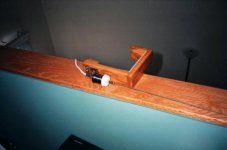
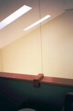
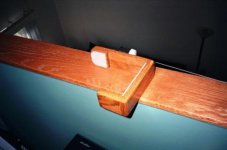
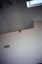
I promised some Pictures of what I did with my ST-2 for attractive indoor mounting. We live in a Townhouse that is on the second floor and we have a loft on the third floor so I put it up as high as possible for all to see. We can't mount it outside as per the Co-op Association.
Here are a few Pics:
Regards//Keith
Fantastic! I guess all in all, it wasn't really that expensive either! Now, don't forget to remove the Balun and scratch the 300 ohm antenna connection and add a 75 ohm panel mount F connector (high quality) directly from the PCB to the connector. That will pull in the stations better that are on the edge.
Also, You can do one more improvement but this really should be done by a FM Tuner Pro. Replace the filters (more narrow and higher quality) and have it aligned.
Then the antenna as you said you are doing. Use only high quality RG6 cable with quality connectors and Nirvana!
I promised some Pictures of what I did with my ST-2 for attractive indoor mounting. We live in a Townhouse that is on the second floor and we have a loft on the third floor so I put it up as high as possible for all to see. We can't mount it outside as per the Co-op Association.
Here are a few Pics:
Regards//Keith
Attachments
Thanks for the pics Keith,
You should be able to pull in some stations with that set up, I may have to install mine outside
I have a 2 story home and the system will be on the main floor.
Where can I buy a High Quality 75 ohm panel mount F connector?
As for the filters Mike at FM tuner told me for a start to replace one of the 4 filters with a 150,
that wouldn't be that difficult....
Thanks
Slate
PS. You know it would not be that difficult to install iec power cord system......
Hi Slate,
I wish I could put the antenna outside and high!
I certainly endorse replacing the Power cord all the way to the Transformer. That means IEC Inlet, Internal wiring and a High Value Power Cord (email me if you want to know who I like and use for both Power Cords and ICs and very reasonable with Eichmann Bullets on the ICs).
But the Power Cord will have the least impact on the sound compared too all the other things you are doing or have done. It may impact the Bass even more and open it up with more air and presence. But it might also be so slight that you might not notice too much. I believe you will hear an impact. It made a big impact on my Amp!
Go for the Filters! How did you get a hold of Mike?
I'll look into the connector some more and post a hyperlink!
Regards//Keith
Slate,
Take a look at these two (they mount differently and try to get gold). If they don't sell just one, find something that works with the way you want to mount it on the back of your TU717 and 75 ohms too:
http://www.mmwavetech.com/shop.net/...rodid=4268&Prodsku=MW-818-G&Prodname=MW-818-G
http://www.mmwavetech.com/shop.net/...rodid=4258&Prodsku=MW-802-H&Prodname=MW-802-H
Email will be sent with IC and Power Cord place hyperlink! Great Value!
Good luck!
Regards//Keith
Hi everyone,
I am planning to do some more upgrades on my tuner ( Sansui TU-717) , I am going to install
an IEC AC Male plug, so that I could run various power cords. The original cord is a lamp cord,
it doesn't have a ground, should I be installing a ground? If so where is the best location to ground?
Thanks
I am planning to do some more upgrades on my tuner ( Sansui TU-717) , I am going to install
an IEC AC Male plug, so that I could run various power cords. The original cord is a lamp cord,
it doesn't have a ground, should I be installing a ground? If so where is the best location to ground?
Thanks
- Status
- This old topic is closed. If you want to reopen this topic, contact a moderator using the "Report Post" button.
- Home
- Source & Line
- Analog Line Level
- Tuner Capacitors