Hi does anybody know how to read the circuit attached, I'm trying to find out how to work out the max and min Gain for each circuit,
can anyone explain what is going on in this circuit
the part that is comfusing me the most is the capacitor. i'm trying to find out how the circuits reacts to various frequecies
If anybody can help i would be very greatful
can anyone explain what is going on in this circuit
the part that is comfusing me the most is the capacitor. i'm trying to find out how the circuits reacts to various frequecies
If anybody can help i would be very greatful
Hi does anybody know how to read the circuit attached
Hi does anybody know how to read the circuit attached, I'm trying to find out how to work out the max and min Gain for each circuit,
can anyone explain what is going on in this circuit
the part that is comfusing me the most is the capacitor. i'm trying to find out how the circuits reacts to various frequecies
If anybody can help i would be very greatful
i cant seem to attach the picture of the circuit, if anyone can help could i email it to you
Attachments
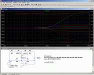
You can easily simulate the circuits using switcherCAD- a free spice simulator that will show you exactly what is going on.
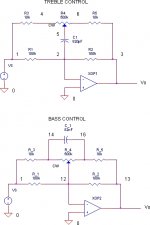
The first circuit is a treble control that provides +/- 17 dB or so of boost/cut in the audible frequency range.
The other circuit is supposed to be a bass control circuit that can be simulated the same way, but it doesn't seem to work. Better check that one.
I_F
The first circuit is a treble control that provides +/- 17 dB or so of boost/cut in the audible frequency range.
The other circuit is supposed to be a bass control circuit that can be simulated the same way, but it doesn't seem to work. Better check that one.
I_F
Attachments
I'll try to explain the circuits without a lot of math.
First you need to understand that a capacitor has a high impedance at low frequencies, and a low impedance at high frequencies. So, to simplify the circuit to help to understand it, we will replace the capacitor by a open circuit (no connection) at low frequencies, and a short circuit (a piece of wire) at high frequencies. We won't worry about what happens in the middle for now.
Let's look at the treble circuit first. The opamp is a basic inverting buffer, with gain equal to -Rf/Ri (feedback resistance / input resistance). We'll ignore the negative sign for this. But just remember that the output will be out of phase with the input.
At low frequencies, replace C1 by an open circuit. Then Rf = R2 and Ri = R1, so gain is R2/R1 or 1. There is also a 500+10+10 k resistance between the output and input, but it doesn't affect the gain of the circuit, because it doesn't connect to the input pins of the opamp. So the gain for bass frequencies is 1. Bass is unaffected by this circuit, no matter where the pot is set.
At high frequencies, think of replacing C1 by a wire. Now the pot, R4, is part of the feedback circuit. So let's look at what happens when the pot is centered. There will be 250k on each side, and both sides are exactly the same. So then Rf = Ri and the treble gain is 1. But when turned fully CW, there is 0 on the left side and 500 k on the right, so Rf = 100k//(500k+10k) = 83.6k and Ri = 100k//10k = 9.1k. So treble gain = 83.6/9.1 = 9.2 or +19.3 dB. This is the maximum treble boost. [The // means "in parallel with", and dB = 20*log(voltage Gain) ]. When turned fully CCW, the treble gain can be calculated to be 9.1/83.6 = 0.109 or -19.3 dB. This is maximum treble cut.
The frequency at which the boost/cut begins to have effect is determined by the value of the capacitor.
You can figure out the bass circuit yourself the same way.
How to work it out
First, 3 khz is not a number of frequencies. 3 khz is the frequency. However, it sounds like you may be asking about the frequency response to the spectrum of frequencies that would make up the harmonic content of the input signal if this were say, a guitar amp circuit.
I'm not an expert so I'm going to advance an answer here with the full expectation that the more knowledgeable forum members will pounce on any incorrect assumptions on my part.
A filter circuit is going to pass or reject a band of frequencies based on the parts used to construct it. So within a particular band, (gap, range) you will pass or reject say- 2200 khz to 3500 khz and as the variable control, (potentiometer) is rotated, the frequencies passed will change, up or down.
colorcat
- Status
- This old topic is closed. If you want to reopen this topic, contact a moderator using the "Report Post" button.
- Home
- Source & Line
- Analog Line Level
- Active filter/Tone control