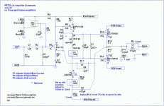
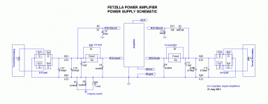
Here's what I've collected and to the best of my knowledge it's all the latest renditions .
The BOM I used as a general guide and ordered resistors and other components to my preferences . not quite sure who that came from . Use at your own risk .
Enjoy , Woody
Folks,
My sincere thanks to Woody, this is the complete FetZilla documentation endorsed by me, now made 'sticky'.
I have also appended here a complete distortion analysis of the FetZilla. Two highly competent EE friends of mine here in Melbourne took distortion measurements of the FetZilla on Monday 27th Feb 2012. They are taken at 1KHz, into an 8R resistive load, at outputs respectively of 1W (+10dB), 13.3W (+20dB), and 26.5W (+23dB):
Fundamental 10.00dB Fundamental 20dB Fundamental 23dB
H2 -93dB 5.012E-10 H2 -78dB 1.585E-08 H2 -78dB 1.58489E-08
H3 unmeasureable H3 -93dB 5.012E-10 H3 -88dB 1.58489E-09
H4 unmeasureable H4 -105dB 3.162E-11 H4 -93dB 5.01187E-10
H5 unmeasureable H5 -102dB 6.31E-11 H5 -103dB 5.01187E-11
H6 -96dB 2.512E-10 H6 -106dB 2.512E-11 H6 -110dB 1E-11
H7 unmeasureable H7 -110dB 1E-11 H7 -101dB 7.94328E-11
H8, H9 and H10 are all unmeasureable
THD by voltage 0.00274% (1W, +10dB); 0.01284% (13.3W, +20dB), and 0.0134% (26.5W, +23dB)
Measurements below about -80 dB can be assumed to be insignificant except in ultraclean designs
These figures are surprisingly good, but with output bias set to 370ma the first 5.5 watts of output are in Class A, so perhaps not so surprising after all.
I would add that the THD does not correlate well with the sound qualilty; rather, it is the profile of the distortion artefacts that affect the perceived sound quality for the human ear.
Not bad for a jfet, two mosfets, and two lateral output fets - only five active devices in total!
My thanks to Graeme and Paul for generously giving their time to measure the FetZilla!
Cheers,
Hugh
Attachments
Last edited by a moderator:
Hi Hugh,
I think the latest Schematic for the PSU can be seen in post 383 of the "Swordfishy/ASPEN FETZILLA power amp" thread Here, where R5 = 10 Ohms rather than the 100 Ohms in this thread. I'm not sure if there are other differences between the versions there and here.
Cheers,
Ron
P.S. My own Fetzilla build has hit a bit of a roadblock at the moment, but more of that later....
Ron,
You are quite right; in the later version, post #383, I moved to a lower value because I found that the bass was more prominent this way.
No other changes to the sound however, but no one I know passes up more bass!!
You are no doubt reserving your build for the warm summer months!!
Good luck with the project, and thanks for your post,
Hugh
Because we are endeavouring to reach 'better sound', according to subjective measures, NOT 'clean up the power rail' if this appears to reduce bass.
Remember, this was designed by dedicated subjectivists with absolutely no technical clue, my friend....... go ahead, clean up the power rail, it will undoubtedly improve the specs, after all!
Hugh
Remember, this was designed by dedicated subjectivists with absolutely no technical clue, my friend....... go ahead, clean up the power rail, it will undoubtedly improve the specs, after all!
Hugh
Where did this come from?........ NOT 'clean up the power rail' if this appears to reduce bass.
Andrew,
If you increase R5 to match the 100R on the other rail, you reduce the half wave rectified 'ripple' and thereby improve the quality of the DC, clean it up, if you will.
Correspondingly, if you leave R5 at 10R and boost the associated capacitor by a factor of ten to preserve the time constant, again, you clean up the rail, no question.
BUT, in both cases, for reasons uncertain, you lessen the bass delivery. Hence the decision we took.
Another reason for this misunderstanding might be that your comment here:
looks very like you are laying down the gauntlet, and I reacted accordingly.
Unfortunately, I say what I say, without ambiguity, and where doubt exists about why, I also say so. I'm certainly not the smartest sausage on the barby, but I strive to do my best.
Cheers,
Hugh
If you increase R5 to match the 100R on the other rail, you reduce the half wave rectified 'ripple' and thereby improve the quality of the DC, clean it up, if you will.
Correspondingly, if you leave R5 at 10R and boost the associated capacitor by a factor of ten to preserve the time constant, again, you clean up the rail, no question.
BUT, in both cases, for reasons uncertain, you lessen the bass delivery. Hence the decision we took.
Another reason for this misunderstanding might be that your comment here:
why bother fitting C12 or even the RC filter if it does not clean up the power rail
looks very like you are laying down the gauntlet, and I reacted accordingly.
Unfortunately, I say what I say, without ambiguity, and where doubt exists about why, I also say so. I'm certainly not the smartest sausage on the barby, but I strive to do my best.
Cheers,
Hugh
Last edited:
......... in the later version, post #383, I moved to a lower value because I found that the bass was more prominent this way.
makes no difference whatever to the sound quality.....
why bother fitting C12 or even the RC filter if it does not clean up the power rail.
NOT 'clean up the power rail' if this appears to reduce bass
I read confusion in these answers/replies.If you increase R5 to match the 100R on the other rail, you reduce the half wave rectified 'ripple' and thereby improve the quality of the DC, clean it up, if you will.
Correspondingly, if you leave R5 at 10R and boost the associated capacitor by a factor of ten to preserve the time constant, again, you clean up the rail, no question.
BUT, in both cases, for reasons uncertain, you lessen the bass delivery.
First, reducing the R improves the bass.
Next, increasing the C does not change the sound
Then the following all say reduces the bass, if the time constant is maintained at it's original value.
I found that increasing the C to bring the time constant back up to match the other side and to match the original seemed to me to give a slight improvement in the bass response/sound.
Sorry Andrew,
Your findings, not mine. If you leave the cap at 100uF, but reduce R5 to 10R, bass is better, but time constant is far shorter than if R5 had been left at 100R.
Kapitz?
Hugh
Your findings, not mine. If you leave the cap at 100uF, but reduce R5 to 10R, bass is better, but time constant is far shorter than if R5 had been left at 100R.
Kapitz?
Hugh
Last edited:
Hi Woody/All
I think I found a mistake on the PS schematic on post 1, C17 and C18 polarity. I think the correct one on post 383.
Regards,
Rom
I think I found a mistake on the PS schematic on post 1, C17 and C18 polarity. I think the correct one on post 383.
Regards,
Rom
Thanks Rom,
I agree; you are quite right. Accordingly I have amended the gif, and deleted the pdf which takes more time to amend.
I hope this is the very last mistake of this project! My apologies for inconvenience, though I note the polarities on the pcb are correct. All in all, the FetZilla is now well documented.
Cheers,
Hugh
Regarding the rectifier diodes,does they need a heatsink?
hey meanman , when i was building my first fetzilla , i was running it open on a bench and could barely detect any warmth , let alone enough heat to require heat sinks . ymmv
build it and see for yourself . they can always be added if you find it necessary .
good to see some more folks building these . a lot more boards were sold than people building them .
you won't be disappointed 🙂
cheers Woody
This is the current state of one channel.Maybe this weekend I'll start up the amp but first I've to build a light bulb tester.Do I need to set the trimpots first before aply the voltage
Attachments
Last edited:
No, should be just fine without special care; it's set up to prevent the output stage going overcurrent regardless of setting.
Keep going, MM, nearly there.....
Hugh
Keep going, MM, nearly there.....
Hugh
So no need to set for example the bias pot max resistant,offset pot half way etc.?Can I clean the pcb with alcohol?
Yes, no problem, set to halfway by all means. Clean with alcohol then polish with a stiff brush, and then lacquer with protectant... to protect from moisture.
Cheers
Hugh
Cheers
Hugh
- Home
- More Vendors...
- AKSA
- Fetzilla Build Documentation


