Hi Supernet, MM,
This is what I thought; that SMPS caps are optimised and additional caps are not a good idea...... the problem for the amp however is that earth returns from the speaker driver must pass through the filter caps, from rail back to ground. Since the SMPS oscillator is around 40-100 KHz, the output caps are quite small, normally no more than 1000uF and usually much less.
The issue then is that the speaker driver earth current much pass through this small cap, and effectively a small cap will increase the Esr over a 4,700uF cap and thereby reduce the damping factor significantly.
I wouldn't throw cold water onto the idea, however, because it may not hurt the bass response anyway. Only a listening test will reveal this.
The clear advantage of low ripple, low hum and low cost is attractive. Does your smps feature power factor correction? If not mandatory in EU, it will be soon.....
Cheers,
Hugh
Member
Joined 2009
Paid Member
I don't know much about SMPS but I thought it was essentially a regulated output. In this case the speaker return current doesn't have to rely on the filter caps in the supply, it will return to ground through the active devices in the SMPS - the power supply will act like a shunt regulator of sorts. IF I'm right, it should be a non-issue.
I like the idea of using the SMPS type supply, much lighter chasis for a given power capability. You just don't want the switching frequency getting into the amplifier if there are rectifying junctions in there, or escaping down the power cord or signal input to upstream components so good filtering is recommended and placing the module in a screened ventilated box inside the chasis strikes me as a good idea too.
I like the idea of using the SMPS type supply, much lighter chasis for a given power capability. You just don't want the switching frequency getting into the amplifier if there are rectifying junctions in there, or escaping down the power cord or signal input to upstream components so good filtering is recommended and placing the module in a screened ventilated box inside the chasis strikes me as a good idea too.
Last edited:
Today,I've tested my second FetZilla with a 300 Watt SMPS with 2x35Vdc.I can't say to hear any different sound.At high volume the SMPS stays rock steady at 35Vdc
What brand of SMPS did you use, where to get it and the price please?

koldby
Koldby,
Those SMPS I bought come from Connexelectronic and bought in France.Someone I know had bought a SMPS from Connexelectronic and he had the fortune not to pay import taxes.
I think there are two kind of SMPS supplies.The ones for when just need power and the ones for audio.The ones sold by Connexelectronics are special for audio.
When SMPS Fetzilla version is completed it will be going to my brother for testing.He has a Fetzilla with a conventional PSU.He had done enough listening to see if there is any differents in sound are performens between the two versions.I didn't test enough but I tought there was an increase of detail in the sound.
My amp boards and SMPS will be mount in the same housing without any screen between them.This way we will know if this has any affect due radiation.
Last edited:
Hi Meanman and Hugh, My fetzilla is up and running. Thanks all the help and plans..... sounds real good, deeper bass is the first thing I see as compared to my F5, two different sounds for two different kinds of music. Louder at low volume settings also, have it running through glass audio preamp but wll try next hooked up to B1 and see what it sounds like. Strong bass is my first notice.
Once I got my hands around how to adjust, it all went together so easily so let me encourage other builders to jump right in.
I would post pictures but I lost the front cover of my chassis, so running without front cover and could not figure out how to post pics on the thread.
Anyway, thanks again John
The sound will get better after it warmed up.
Guys,here you can read atest of the SMPS Connex SMPS300RE | H i F i D U I N O
Guys,here you can read atest of the SMPS Connex SMPS300RE | H i F i D U I N O
Hi Hugh,
Nice to be discussing this design again though I tend to think the DF factor issue will be OK with the SMPS. JLH stated that regulated supplies tend to give "firmer" bass.
Personally, my concerns on this supply are more about the impact on sonic quality due to HF noise, both directly injected & radiated and reading the report from meanman above about "more" detail does not necessarily re-assure me. Adding noise can often give the "effect" of more detail but lessen the subjective fidelity.
However, with a SMPS we know we have to focus our noise reduction efforts at very high & specific frequencies which might make things easier but I would also want take a very careful look at the earthing arangements. I prefer my system ground to have good AF, HF, RF isolation from mains earth.
I would love to be able to replace the massive choke regulated supplies I use on my fetzilla and definitely intend to check out this SMPS to see if it works for me. If it does I might be able to reduce my PSU mass by 75% !
cheers
mike

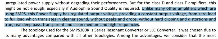
Further fodder for our consumption:
http://www.audiophonics.fr/images2/6189/SMPS300R.pdf
I don't know that much about switch mode design so I'll get some expert advice on this but I don't like the look of the 100nF cap across 10R connecting system ground to mains ground. In my conventional supplies I just have 100R in this position . . . . ahh further down the datasheet it says that there is a link the bottom of the board that makes this optional - this is encouraging
Thx for your comments meanman but I should say that I now regard some of my input in the original thread as uninformed hogwash !
In particular, having now tried O/P chokes I find that they play a very valuabe role with this design by increasing stability in the feedback loop and thereby improving the subjective sound - Thx Hugh
But about very low noise PSUs my views remain unchanged
cheers
mike
Last edited:
Just to mention...not all SMPS are regulated. If we have unregulated SMPS this is simple DC-DC converter, without feedback. So it is similar than classical PSU. For audio, I would rather recommend non regulated one. Also it should be made exactly for audio, that means that filtering is much more improved, also against noise injected back into mains. Actually a good audio grade SMPS should not look much different on osciloscope than classic PSU, but the advantage of using first one is huge. Dynamic, headroom, bass definition are simply superb to classic PSU.
But it is important, not to use any aditional capacitors between amplifier boards and SMPS!
But it is important, not to use any aditional capacitors between amplifier boards and SMPS!
Every PSU has some degree of regulation and this one seems to have quite a high degree of regulation.
The issue often discussed is wether there is regulation involving loop feedback but this issue has different parameters and significance in a SMPS.
If less regulation is desired some series resistance can be added.
I think I'm gonna buy a couple of these units to see how they perform.
The issue often discussed is wether there is regulation involving loop feedback but this issue has different parameters and significance in a SMPS.
If less regulation is desired some series resistance can be added.
I think I'm gonna buy a couple of these units to see how they perform.
Attachments
Case < SMPS and heatsinks < quiescent currents and rails
Hi
Until I can reclaim some ongoing workbench space and get soldering, I’m making my way through the threads, looking into *all the parts etc - including the case
SMPS: assuming further reports & tests are encouraging, I want to get a case big enough to fit the SMPS. The SMPS300RE is a PS for *both channels, right?
I’m working back: case < heatsinking < quiescent current - and rails.
I want to be able to run higher quiescent currents, inc what Greg found it sounded best at: 1 A.
Forgive me if this has already been discussed:
A heatsink rated 0.42 C/W is right for 500 mA with 36 V rails, or 1 A with 24 V rails.
With 1 A, what would be the output and ability to drive lower impedance loads with rails of either 24 or 36 V?
While the Fetzilla boards were (I believe) sized to run on a 0.42 C/W heatsink, if running 1 A with 36 V rails, what rating heatsink would be sensible?
Thanks
Otto,
If you run 1A through the output stage, you will be dissipating 2 x 36 = 72W from each channel if your rail voltage holds up.
This is a lot of heat. If we assumed a max ambient temp of 35C, and a max heatsink temp at 65C (just on the limit of holding your fingers on it), then you are warming it 30C above ambient.
For a heatsink rising from 35C to 65C for 72W, and note that TWO heatsink, well apart, are required for a stereo amp, you need a 30/72 = 0.42 C/Watt, which will be at least 300m long (12 inches) and 75mm tall (3"). This is a minimum requirement. If the thermal capacity is better than 0.42C/watt, say 0.35C/watt, this would be better.
Cheers,
Hugh
Hi Hugh
Thank you for your prompt response!
And at 1 A, would there be a difference in output and/ or ability to drive lower impedance loads with rails of either 24 or 36 Volts?
At 1 A, do you know what the class A watts would rise to?
Did Greg post his specific thoughts on the aspects he preferred in sound at the higher current?
Cheers
Hi Otto,
At 1A quiescent the Class A mode would be much more. Using LTSpice, it reveals that output rises to 22.6Vp for inactive side to turn off, which represents to 45.2Vpp into 8R.
Corresponding, this is 31.9W Class A - a very impressive figure.
At 24V rails the output devices would each be dissipation 24W rather than 36W. This is a far better loading. This change would mean that essentially the output would drop to 17.4Vp max, but with quiescent adjusted to 1A again this too would be in Class A, which is 18.9W.
To change to 1A quiescent current, you might be to greatly increase the value of the resistor in the diode string on the bias generator. For 36V rails it would increase to 295R, and with 24V rail it rises to 520R. A 500R trimmer and 47R resistor would be a good change to accommodate this.
Yes, the sound will change, since the distortion profile would skewed to lower order harmonics, H2+H3+H4. It would sound very tubey....... of course, no guarantee that everyone would like this.
Cheers,
Hugh
- Status
- This old topic is closed. If you want to reopen this topic, contact a moderator using the "Report Post" button.
- Home
- More Vendors...
- AKSA
- Swordfishy/ASPEN FETZILLA power amp