Scooperman,
It's always best to wait a bit before commenting further. I've enjoyed a good sleep and thought it through a bit more.
Thank you for your comments. Well put and noted. Here are your comments.
The core of this problem is the silkscreen, and it was compromised by the software used (Protel) and the treatment by the maker (Greentek Electronics).
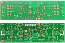
I have attached two images; one is the original pcb silkscreen overlay in two parts left and right as designed, and the other is a scan of the pcb on receipt. You can very clearly see that the pcb overlay is subtly different to the original, which I submitted. Most of the errors identified are not evident in the original. I was disappointed to say the least, and five of your criticisms above were outside my control. Fortunately none of the errors compromised performance though they do affect component identification marginally.
FetZilla and FetZila are different because the software will not accept eight letter headers on the file number, only seven!! There is a reason even for the spelling error, outside my control!
Non-standard footprints, which ones particularly? The 3W smds perhaps? We are dealing with unusual components here; the thick film resistors, the Auricap input capacitor, the output inductor, and the enlarged 'Mars Attack' pads on the jfets. I composed these primitives myself according to past experience, so if you think some are wrong, do let me know and I will revise them.
I amended the BOM to reflect P1, P2, and P3 trimpots. Thanks for picking that up, I missed it!
You are right on D1/2 and D7/8. They are indeed different; yet the devices are all 1N4004.
Lastly, components on wrong side of board; yes, true enough, this primitive was set up for component side mounting and I did not revise it for foil side, my mistake.
On balance, however, silkscreen errors aside, this is a good pcb, with extremely good noise performance and a compact profile, highly suited to an analogue application and easy to build. It is nothing like the digital boards produced by Vigilant Products, which appear to be tightly disciplined masterpieces built to a completely different set of conventions however.
Scoop, thank you for your input, and your subsequent pleasant post,
Cheers,
Hugh
It's always best to wait a bit before commenting further. I've enjoyed a good sleep and thought it through a bit more.
Thank you for your comments. Well put and noted. Here are your comments.
Silkscreen is erratic, e.g. placement, orientation, font size changes with component size.
Overlapping placement outlines. (Not a big deal for hand insertion.)
Placement outlines and silkscreen on wrong side of board: R22,23,24,25.
Identical components with different outlines: D1,D2 different from D7,D8, and C8 different from C7.
Components missing from BOM: P1, P2,P3.
Surface mount components R22-25 not called out on BOM.
Product name spelled differently on opposite sides of pcb. Fetzilla/Fetzila.
Nonstandard component footprints.
The core of this problem is the silkscreen, and it was compromised by the software used (Protel) and the treatment by the maker (Greentek Electronics).
I have attached two images; one is the original pcb silkscreen overlay in two parts left and right as designed, and the other is a scan of the pcb on receipt. You can very clearly see that the pcb overlay is subtly different to the original, which I submitted. Most of the errors identified are not evident in the original. I was disappointed to say the least, and five of your criticisms above were outside my control. Fortunately none of the errors compromised performance though they do affect component identification marginally.
FetZilla and FetZila are different because the software will not accept eight letter headers on the file number, only seven!! There is a reason even for the spelling error, outside my control!
Non-standard footprints, which ones particularly? The 3W smds perhaps? We are dealing with unusual components here; the thick film resistors, the Auricap input capacitor, the output inductor, and the enlarged 'Mars Attack' pads on the jfets. I composed these primitives myself according to past experience, so if you think some are wrong, do let me know and I will revise them.
I amended the BOM to reflect P1, P2, and P3 trimpots. Thanks for picking that up, I missed it!
You are right on D1/2 and D7/8. They are indeed different; yet the devices are all 1N4004.
Lastly, components on wrong side of board; yes, true enough, this primitive was set up for component side mounting and I did not revise it for foil side, my mistake.
On balance, however, silkscreen errors aside, this is a good pcb, with extremely good noise performance and a compact profile, highly suited to an analogue application and easy to build. It is nothing like the digital boards produced by Vigilant Products, which appear to be tightly disciplined masterpieces built to a completely different set of conventions however.
Scoop, thank you for your input, and your subsequent pleasant post,
Cheers,
Hugh
Attachments
Ron,
I have had the FetZilla running on my test bench for more than a week now and can say that there is no need to mount the three bias diodes on the foil side.
It was an option I considered for very hot climates, but I believe it's unnecessary after living with the amp for some time and noting that the quiescent was rock steady, better in fact than any bipolar output stage I've worked on.
Accordingly, mount them all on the component side, it is no problem at all as the tempco of the lateral fets keeps everything very controlled. I set my quiescent at 400mA.
Cheers,
Hugh
Scooperman,
It's always best to wait a bit before commenting further.
........
Cheers,
Hugh
Absolutely true. My wife taught me that lesson. Still hurts.
Cheers back to ya!
Hugh,
I found that an important information is missing in your construction guide that should be included for people with less experience. It is important to mention that both output devices should be electrically insulated from chassis using thermal pads between device and heat-sink. Source of Exicon MOSFETs is connected to the case. SIL-Pad K10 or similar thermal pads for TO-247 case can be used here.
George
KLewis found a good part for the spade lugs, the Keystone 1287 has .045" lugs and the pcb holes are .050". But I still have not found suitable fuseholder clips. The Keystone, Cooper-Bussman, and Littelfuse parts have .060" to .064" lugs, and the pcb holes are .050". I may give up and just buy what I can find, and grind the lugs to fit.
")
hi Woody. Ken (KLewis) posted a pdf parts list for ordering from Mouser, this is in post #254. I started using his list because I order small lots from Mouser. If you are using the Mouser catalog, you will find some components on his list which are not in the printed catalog, however they do show up on the Mouser website. So my list is a copy of Ken's list, so far. If I get energetic I will type it into Excel. I have no idea how to link a file here.
Starting at around the 20th page of this thread, various questions and answers about specific components start being posted. In post 200, Hugh suggested USA supplier Hosfelt for mica caps. Then I recall poster AndrewT saying mica caps aren't needed. Then in another post (which I now can't find) I think it was Hugh again but saying exactly the opposite. My intention is to re-read all of it, but this time taking notes.
hope some of that was helpful
Folks,
Thanks for all the interesting posts. Nicola, I'm delighted your boards have arrived in Italy, I hope you get the amp running very soon. George, beautiful work, stunning quality. I use BYV32E-150 ultrafast soft recovery diodes from Philips. Don't forget the back to back diodes and 10R resistor for chassis earth. Yes, good point on the insulation of the outputs. As an old hand I simply assumed everyone would use insulating washers on the outputs, but you are right, it should be formally mentioned.
Atilla, I agree, I think there is a market niche for an all FET amplifier. Perhaps this is the DIY infant brother of an Ayre?
Scoop, I thank Ken Lewis and you for BOM links. I will admit this aspect is laborious and after all the documentation I was disinclined to do it myself, particularly as I source a good many components locally - no doubt made in China - and my market in the southern Pacific is very different to the US and European experience.
Fran, I always overcool my amplifiers and go for huge heatsinks. In the height of summer we have experienced temperatures of 47C in Melbourne, even more inland, so this is understandable. But clearly heatsink size could be much reduced in countries where the highest temperatures seldom exceed 30C, such as your own. I have used a nominally 0.37C/W sink, derated to 0.42C/W at a more reasonable 25C, to cool ONE channel, but the pcb is 230mm long and thus unsuitable for two on the one heatsink. You could likely reduce the length of the heatsink from 12" to the length of the pcb - 9" - without any thermal issues. Width should however exceed the width of the pcb for packaging reasons, namely 3". Tani, thank you for pointing the way on this.
Scoop, can't help on fuseclips unfortunately, but yes, silver micas are the go. I prefer them as they are available cheaply in a wide variety of sizes from Hosfelt in OH, but they seem to perform well in audio amps. I'm sure film polystyrene would be good too, as their DA is lower still.
Ken, my sincere appreciation for your excel spreadsheet. It addresses a clear need for this build, thank you!
In about a week, when all present boards are accounted for, I will start a second group buy on the FetZilla. I'm hoping by then enthusiasm will fire up again because many people will have experienced the sound quality of this amp, and will know it's every bit as good as others have said. If we have an all FET amp that has been built by 40 people and verified both easy to build and very good sounding, there should be more interest.
Cheers,
Hugh
Last edited:
for those in the usa , this should be more than adequate to cover heat and allow enough height for toroidal's 10.080" Wide x 4" Long Heatsink - HeatsinkUSA, LLC Store
summer's over and daughter's finally off to college . wife mentioned tonite that we need to get going on projects hehe
summer's over and daughter's finally off to college . wife mentioned tonite that we need to get going on projects hehe
Where are you looking? These are standard 1/4" x !" PCB fuseclips and fuses AKA type 3AG. Mouser # 504-1A1120-10 is close, but a better type clip has an end stopper to avoid misalignment. i.e. their illustration G rather than R as listed. These are so-oo common and been around longer than most of us.found a Camden fuseholder with a 1mm pin, but its for a 5x20mm fuse. Still looking.
'Guess I should say source will be Taiwan, China etc. and sizes may be more suitable from them.
Last edited:
Scoop,
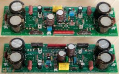
I have used this fuseholder but had to modify it by cutting one leg and trim another (hole on the board is too small) fit on the board. You can see it on the picture of my board posted today.
BK/1A1907-05 Cooper Bussmann Fuseholders, Clips, & Hardware
George
I have used this fuseholder but had to modify it by cutting one leg and trim another (hole on the board is too small) fit on the board. You can see it on the picture of my board posted today.
BK/1A1907-05 Cooper Bussmann Fuseholders, Clips, & Hardware
George
- Status
- This old topic is closed. If you want to reopen this topic, contact a moderator using the "Report Post" button.
- Home
- More Vendors...
- AKSA
- Swordfishy/ASPEN FETZILLA power amp