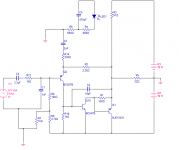
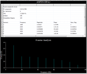
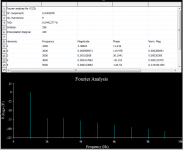
John,
You are talking of gross clipping, at around 6Vp due to current limiting!! This is an SE amp, of course this is a problem - Andrew points this out earlier. It is, like all topology, a compromise..... but most people will not be listening at 3.07Vp on a 24R can. High Z cans are no problem to about 10Vp, in fact.
My comment about distortion obviously relates to the rated 1Vrms, the 0dB standard, where you get a distortion profile hardly any different to the CCS loaded one. Obviously the CCS confers flexibility for all sorts of cans, and that is the purpose. I have attached the distortion profile for a 91R resistively loaded output at 20KHz signal into 24 + 10 ohm load at 1Vrms, which is 1.414Vp.
I thought you said you were leaving?
Hugh
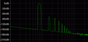

Last edited:
Member
Joined 2009
Paid Member
This is Hotel California - nobody can leave. And a good thing too.
The resistor CCS is the simple option, allows swings closer to the upper rail. But if we were to go passive, why not an Inductor - it's the most efficient option ? Or is the dc bias current going to make the Inductor an expensive monster ?
The resistor CCS is the simple option, allows swings closer to the upper rail. But if we were to go passive, why not an Inductor - it's the most efficient option ? Or is the dc bias current going to make the Inductor an expensive monster ?
About that inductor - perhaps we could make a "plasma" switch, which sends it into oscillation, effectively becoming a tesla coil at several MHz, burning out all that plastic garbage from the headphones and turning them into full-blown plasma transducers...?
Sounds feasible to me...
Anyways, it would be interesting to use something other than a real CCS, just to make the circuit a bit exotic, but... (BTW I'm all for the inductor if it proves feasible; it's more linear than a CCS at least)
- keantoken
Sounds feasible to me...
Anyways, it would be interesting to use something other than a real CCS, just to make the circuit a bit exotic, but... (BTW I'm all for the inductor if it proves feasible; it's more linear than a CCS at least)
- keantoken
John,
You are talking of gross clipping, at around 6Vp due to current limiting!!
I thought you said you were leaving?
I come and I go,
I'm pleasant and I'm nasty,
And apparently I'm smart and I'm stupid...
You are right, of course, I didn't even bother to check if it was clipping - just assumed that it wasn't and ran the FFT.
With that said, input sensitivity is very low, less than 1Vpp to before clipping might be too low, unless you have something attenuating at the front that I don't know about?
Good point, Gareth.
John,
The pleasant and smart we can handle. The stupid is forgiveable, the nasty is challenging. OTOH, we can all ignore you if you turn into Freddy Kruger.....
It would be nice to have an amp which sounds 'nice' when it's clipping. That would be quite a coup. Any ideas? We could start with tubes!
Yes, in front of the amp is volume, balance, tone and crossfeed. Tone has gain of 6dB, all the others severely attenuate and this is the reason for the highish gain and resulting low overload margin.
Getting all circuit blocks together is the next step in the design process.
Nico, can you advise please on a crossfeed circuit at the front of the amp, rather than at the end?
Kean,
We would need at least an inductive reactance of 34R at 10Hz, yielding a 6dB point at this frequency and 125mA. This equates to L = Xl/2piF, which is 540mH, with a DCR giving say 2V drop at 125mA corresponding to 16R. It would need to be gapped, increasing core size, to prevent saturation. This would be large, perhaps an EI cube around 3" or more on a side. Cost would be on the order of $US80 minimum. It is not practical, unfortunately. Furthermore, it would have capacitive losses unless very carefully wound, leading to loss of HF response.
Cheers,
Hugh
Member
Joined 2009
Paid Member
It would be nice to have an amp which sounds 'nice' when it's clipping. That would be quite a coup. Any ideas?
I remember Wavebourn had some ideas on this, use of diodes in some strategic locations if I remember.
Hugh - thanks for explaining about the distortion to me, it is interesting how sensitive the ear is to such low levels of the odd harmonics. Also I had not realised why such high speed was beneficial to the reproduction of audio frequencies before.
Kean - thanks for the encouragement
I have been thinking about the simulations and the simulated distortion levels in particular. If we are only interested in currents and voltages then a simulation with an accuracy of tree or four significant figures will be fine for the vast majority of situations. However, if we want to accurately calculate the amplitude of high order distortions which are at -140dB relative to the fundamental we need an accuracy of eight significant figures in the transient simulation from which the harmonics are calculated. It matters whether a voltage is 1.0000000 or 1.0000001. This puts much higher constraints on the accuracy of the simulation. The underlying physical device models need to be very good to give this level of correlation with reality, the model parameters we use need to be very accurate and the simulator needs to take care of numerical effects arising from the computation. I don't really have a feel for how accurate the models used by the simulators are and with this in mind I was wondering what the likely uncertainty is on the simulated values of the harmonics?
Best wishes
Phil
Hi Mj.
Just read your post regarding clipping problem faced by you for designing
a circuit design for your headphone. Clipping do reduce the noise effect,
so its a matter of consideratiion to reduce it and keep it as low as possible.
Thanks for your post and stay connect.
Just read your post regarding clipping problem faced by you for designing
a circuit design for your headphone. Clipping do reduce the noise effect,
so its a matter of consideratiion to reduce it and keep it as low as possible.
Thanks for your post and stay connect.
...and with this in mind I was wondering what the likely uncertainty is on the simulated values of the harmonics?
Best wishes
Phil
That's one of the things I've seen - too much stock put into the simulated spectrum. It has been my experience that the raw THD figure (0.045% for example) is relatively accurate, but the spectrum has not been confirmed and it's accuracy I strongly doubt - it will change, sometimes radically, with a different device model (could be the same device, different manufacturer model).
At best I think it can give a "hint" as to what the spectrum may be if you manage to use accurate models and can get similar results with similarly accurate models on a second simulation run.
Hugh - Just realised I forgot to say anything about your great new circuit! Judging from your simulations the additional gain and negative feedback offer really good performance combined with simplicity - looks like you've been working hard for us again. I also wanted to say that my question about the simulations was asked out of a general interest in trying to better understand things, it is not meant to be a criticism of your simulations in anyway.
John - thinking about it the fact that you see the raw THD figure being more accurate makes sense as it will be dominated by the larger amplitude harmonics which are easier for the simulator to get right. Also being a sum some errors on the individual harmonic components may well cancel out.
Phil
John - thinking about it the fact that you see the raw THD figure being more accurate makes sense as it will be dominated by the larger amplitude harmonics which are easier for the simulator to get right. Also being a sum some errors on the individual harmonic components may well cancel out.
Phil
Here's an example. I used the same circuit but changed one device, in this case the output in Hugh's circuit. I used the MJE350 that was in the Multisim library (I'm not sure where it originated) and I used the MJE350 model from Fairchild.
The MS model:
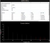
The Fairchild model:
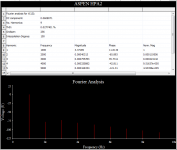
Quite a difference, even in the raw THD number when there really shouldn't be - same circuit, same condition, radically different results.
With that said, Hugh's circuit is a good one for testing the consistency of these models and I believe the harmonic spectrum is fairly accurate, as I have been randomly "plugging in" various known good models and getting nearly the same result. It should be a very good sounding amp.
(pleasant John today )
)
The MS model:

The Fairchild model:

Quite a difference, even in the raw THD number when there really shouldn't be - same circuit, same condition, radically different results.
With that said, Hugh's circuit is a good one for testing the consistency of these models and I believe the harmonic spectrum is fairly accurate, as I have been randomly "plugging in" various known good models and getting nearly the same result. It should be a very good sounding amp.
(pleasant John today
Hi all,
your project seems really great! Btw I just got lost in reading the hundert of posts you already did in this thread..
Maybe somebody could make me some sort of "current status of the project"?
Would help me understand which are the latest schematics/ideas for PSU, crossfeed, HeadAMP and POT you are currently holding.....
And another thing: are you now planning to go with batteries or did I miss something? =D
Thanks!
tent:wq
Phil,
A glance at the models used in LTSpice reveals all parameters are at 6 significant figures. For example, here is the MJE15031 taken from the library with Notepad:
.MODEL MJE15031 pnp IS=7.17489e-11 BF=457.169 NF=1.11376 VAF=6.01557 IKF=0.345808 ISE=1e-08 NE=2.18567 BR=0.247882 NR=1.39549 VAR=60.1557 IKR=0.0263893 ISC=1e-16 NC=2.89486 RB=2.29208 IRB=0.0114006 RBM=0.000102795 RE=0.00815557 RC=0.0407779 XTB=0.1 XTI=0.1 EG=1.05 CJE=1.64037e-09 VJE=0.819491 MJE=0.537987 TF=1.60991e-09 XTF=180.82 VTF=1.16561 ITF=6.50499 CJC=4.82516e-10 VJC=0.4 MJC=0.374287 XCJC=0.786653 FC=0.712788 CJS=0 VJS=0.75 MJS=0.5 TR=3.32795e-08 PTF=0 KF=0 AF=1
What is in doubt is the veracity of these models. I am not skilled in this area, but I'm told there are some glaring inadequacies, for example the Early effect is not prescribed, and behaviour of beta at very low Vce is not accounted for. The expert in this area, a mathematician, is Andy_C, also on this forum. Neither is the Berkeley spice engine transparent; we cannot know if all aspects of transistor operation are incorporated in the computation of THD.
However, my thoughts are that the basic device parameters are accurate and this is useful for back of the envelope scratching during the early stages of design. It enables viability of a topology to be quickly tested and operating points refined. Assuming the distortion artefacts are fully accurate is probably foolish, but in the absence of an AP it's better than nothing, and certainly tells you quite a bit about distortion profile; whether artefacts are same magnitude, or monotonically decreasing, for example. (One might even ruefully consider the stunning correlation, or lack of it, between THD and sound quality, but that is a separate issue!) Since these are essentially command line programs, there is a learning curve not unlike Unix, and some will have very sophisticated analysis techniques, which can lead to a variety of answers, trending simulation towards interpretation rather than unarguable, objective fact. I have also seen quite different results between LTSpice and MicroCap, for example, an outstanding, commercial program used here by Nico, and this would indicate that for thoroughness one should always examine circuits in detail with two different programs, one preferably fully commercial, and therefore very costly. You need the proper tools; you don't go to war in a Fiat Uno.
The real issue is stability. The Bode plot looks pretty good on LTSpice, but figuring the very low value stability capacitors is best done empirically, particularly as it so affects sound quality.
If I spent as much time building amplifiers as I do on this board, I would have completed the project by now. I'm trying to build group participation, but it's very time intensive.
Phil, Earle Geddes, a very smart investigator of distortion measurements and sound quality correlations, has postulated a new metric, the Gedlee parameter, which attaches sharply increasing weighting to higher order, particularly odd, harmonics. This is said to correlate far better with sound quality, and might be worth investigating. I have never been happy about the simple observation that a much vaunted single ended triode amp with 2% THD sounds somehow more pleasing than a 0.01% SS amplifier. This is absurd, and makes a mockery of THD measurement. OTOH, I have always been impressed with Jean Hiraga (Japanese French audiophile from the sixties who developed 'Le Monstre', a legendary amp of only average THD but wonderful sound) and John Linsley Hood, an English nuclear scientist who died recently at 78 and who designed a 10W Class A amp in 1969 (and again in 1996) with lousy measurements but wonderful sound.
John, thank you for your tireless input. You are indeed in good humor today!
Tent, stay posted, main circuit block coming!
Cheers,
Hugh
Hmmm, I feel like I could develop BJT models on commission....

Oh yes... For those who haven't noticed... LTSpice wiki section!
LTSpice and What the New User Should Know - diyAudio
- keantoken
Oh yes... For those who haven't noticed... LTSpice wiki section!
LTSpice and What the New User Should Know - diyAudio
- keantoken
Models from different manufacturers are different, an MJE350 from one manufacturer is not identical to another manufacturer. On Semi is good if you use On semi transistors. Fairchild is good if you use Fairchild transistors. I am stumped when someone develops a model for an MJE350 transistor, which one did they use, how the heck did they make some of the measurements, very sophisticated equipment is required that exists at a semiconductor design plant?
Using a professional simulator with purchased models you get it by manufacturer, not by part name only. Furthermore you should run Monte Carlo to accommodate for the spread of specs of the same components, temperature spread, supply spread and so on. We all know that almost all compo nets characteristics change with temperature, so what temperature is used in these simulations?
Besides semi-conductors you should use models for every component such as capacitors, resistors, op-amps since these contribute considerably to the end result.
A full simulation of a simple amplifier like this runs for more than an hour before reasonable results are available. Changing a component in the circuit could run another hour.
Nothing in life is free, if it is, it is not worth having. You can improve the simulations by running it and changing every component's model data by the best and worse case scenario, but this will take several days, considering the number of iterations that does exist.
Cheap or free programs are just that, if it was worth anything it would not be cheap nor free.
Good luck keantoken and others that say they compiled better models, I would really like to know exactly how would one do that without the equipment to measure it accurately. It would be a enormous task and very nice gesture if you would just start with all the variants of a 100uF capacitor from a few well common manufacturers and provide proper models for it.
If these things were all available, accounted for and used by the free simulators out there then I suggest that they would not be free by a long shot. I feel the same way regarding test and measurement equipment using a PC sound card. PC sound cards would put the likes of Hewlett Packard, Anritsu, Tektronix, Rhode & Swarch, Wiatzu, to name a few completely out of business. I hardly see that happening in industry, but it appears that the PC and free programmes are the audio designers epitome.
- Home
- More Vendors...
- AKSA
- Aspen Headphone Amp
