Salas said:Q2 has Vout-Iq2R4 across it and Vout-Vbe on its base. You can use MPSA94 for it also, and you can keep the shunt NMosfet as hotter on top the load consumption as you feel, only allow for dynamics. The more, the better.
I still don't understand how the constant current circuit Q4/Q5 can work if it only has Q2's Vbe (0.6v) across it. With a resistor of a kilohm or more between Q5 and the base of Q2 (as has already been suggested for HF stability) the circuit would work OK.
My other concern is for the well-being of Q5. Perhaps I misunderstand the circuit, but surely at switch-on C2 is close to a short circuit, which would put a large fraction of the regulated voltage across Q5? It's not clear to me that the shunt MOSFET would protect Q5 with 100% reliability. Perhaps this is the reason for the failure of some implementations of this circuit when Vreg is adjusted too quickly.
Alex
The ring of 2 obviously works, we would have no Vref if it did not.
1k res to the Q2 base compromises transient behavior though.
Wasn't there to see why they had just a couple of bad starts. Maybe. It never kicked on me though. And there are many ''OK no problem'' builds. I would put a base stopper resistor for Q2 (100R) and 12V Zeners between G,S of Mosfets and nothing more. I have suggested such before, If there is a problem. I generally avoid extra parts if something works.
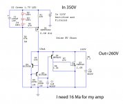
If you need 16mA as noted on the circuit, just make R1 82R 1/4W. In this case there will be 2.5W dissipation on Q1 and 4W on Q3 when 16mA is always drawn. Use sinks on both. With 100R for R5 it looks like giving 265V ballpark with 350V in. But because it normally drifts and stays lower, start with such a fixed resistor so to see if it will need anything different. Let me know when you make it and it is measured for Vout after 15mins supplying your (pre?)amp.
dia thien thai said:
My amp need 260V and 160 Ma
16mA or 160mA?
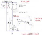
We did not have good feedback with an attempt at high mA from a member here in the past. Had burned components. Our experience is excellent sound and long time working builds around 100mA the most. Anyway, I have prepared for you a circuit with maybe better safety for your purpose. It runs at 185mA, there must be some headroom. It may work OK or it may fail.
The parts cost is cheap if you are willing to take the risk of testing.
You will need a 1C/W heatsink to mount the Mosfets, be sure they are insulated from it. Also don't try it without 160mA load, else the shunt Mosfet will need a very big heatsink for dissipating all the 185mA current alone. Takes practical care and no wrong moves at such voltage and current. Mount the 220R gate stoppers and 470R base stopper directly on the respective semiconductor inputs with short legs.
Attachments
Hi guys  , I'd like to report a little bit of success. After a mini burn fest
  I have arrived at a circuit that seems to behave well. My parts cemetery has received new members
 some beloved mje350s and mje340s, and some beloved 2sk170s, and some beloved mtw20n50e. I was most sorry about the latter, 500V 20A (250W) n-channel mosfets, painstakingly pulled out of some industrial psus. Anywho, to make a long story short, after the previous burn fest I had decided that there's got to be a way to use n-channels mosfets because they come in stronger varieties. And you need strong mosfets for a high power and high voltage shunt
OK, so the design is a variant of yours salas. I butchered it a bit
 I needed a 150V/100mA version, so that's what I optimized it for, but this one I think can be made for even higher voltage/current; in fact while adjusting things I've seen mine draw almost 200mA at 150V, and it didn't die. The visible ripple showed at below 100uV.
  Not bad.
If people are interested I'll post the schematic with some comments.
, I'd like to report a little bit of success. After a mini burn fest I have arrived at a circuit that seems to behave well. My parts cemetery has received new members some beloved mje350s and mje340s, and some beloved 2sk170s, and some beloved mtw20n50e. I was most sorry about the latter, 500V 20A (250W) n-channel mosfets, painstakingly pulled out of some industrial psus. Anywho, to make a long story short, after the previous burn fest I had decided that there's got to be a way to use n-channels mosfets because they come in stronger varieties. And you need strong mosfets for a high power and high voltage shunt OK, so the design is a variant of yours salas. I butchered it a bit
I needed a 150V/100mA version, so that's what I optimized it for, but this one I think can be made for even higher voltage/current; in fact while adjusting things I've seen mine draw almost 200mA at 150V, and it didn't die. The visible ripple showed at below 100uV. Not bad.If people are interested I'll post the schematic with some comments.
Salas said:Please go ahead. There are enough aspiring to high current regs for small amps or larger. Is it relatively simple still?
Thanks! I don't know about simple, that is subjective. It is not crazy complicated though. Preparing the post with figure, coming soon.
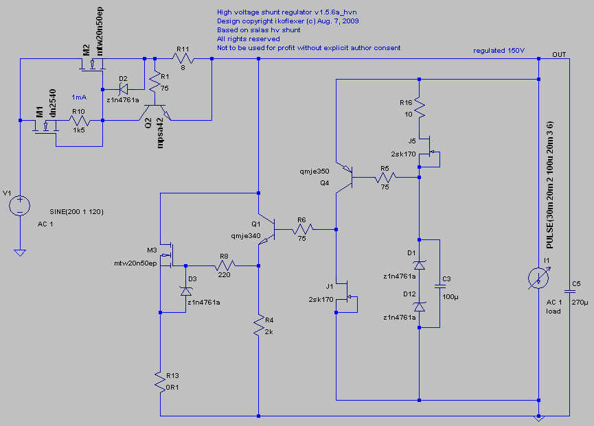
Here it is. I had to abandon my other biasing scheme because it wasn't very safe to setting the bias voltage on the first mosfet, M2. Salas, this will offer no surprises for you, variation on your theme, indeed.
Some comments on the schematic. I'm sure I'll miss something important, but nevertheless...
M1 is a depletion mosfet, wonderful part. The value of R10 is shown as 1K5 but in practice the value depends on the particular Idss of the DN2540. They are not very expensive, the DN2540, and in a high voltage situation like this, IMHO it is a very good part to set a CCS. I set a mini CCS of 1mA by adjusting R10 while the DN2540 was hooked up to a 9V battery. It is nice that at 200V the thing will still pass very close to 1mA, once R10 was adjusted accordingly. I used a 5K trimmer for R10.
The second half of the mini CCS is Q2+R11. Basically this will set the limit on the current that is allowed to pass through the power mosfet M2. Roughly this current can be calculated I = Vbe(Q2)/R11 = 0.6/R11. You need to try a few resistors for R11 until you get the desired current.
R13 is there only to measure the current that goes through the shunt. It is not a necessary part for performance.
I used two 75V zeners to get 150V. To get your own voltage, choose zeners accordingly. The 2sk170 Idss in my case was about 9mA. It does not matter too much as long as the Idss of the 2sk170 is somewhere between 7 and 11mA, but calculate the power that each zener needs to dissipate once you know what current will go through them (P = V(across zener) * I(through zener)).
In my case, with the parts shown, it takes a few seconds for the regulator to reach steady state. There, you now have a built in delay too.
Last, about the heat sinks. They need to be large, and do isolate them from the body of the mosfet (which is the drain), unless you want shock therapy. Each specific configuration (voltage/current out,current shunt) will need to have at the least the power mosfets M2 and M3, and R11 chosen properly.
As final comments, the circuit feeding the regulator that I just built consisted of a transformer, a bridge of four ultra fast soft recovery diodes, and a CGC block (capacitor, simple gyrator, capacitor).
If you are unsure about working with high voltages, then DON'T!!!
I make no claims whatsoever for this simulator; it is your responsibility if you decide to build it.
Edit: as always, comments are most welcome.
Nice. As I see the blocks are: 1. A depletion CCsed Vbe reference for the main Mosfet CCS. Can 10M45 play the role of the DN? I got some. Don't you use gate stopper for the DN in the practical build? 2. Jfet Idss CCsed Zener combo Vref. Could C3 be 1000uF for battling noisier diode parts? They tend to be erratic in batches for noise. Of course 1000uF the higher the V the dearer and bulkier. 3. Jfet CCSed 350 driver. 4. 340 buffer. 5. Shunt. Nodes set for remote sensing.
All in all an HV buffered full NMOS V1 after practical choices and tests. Will be sounding mega. They just don't practice such stuff in tube audio by 99.9% of builds. Is there a picture? Congratulations, you had your share of frustrtions with HV high mA before. About time! Drinking beer?
All in all an HV buffered full NMOS V1 after practical choices and tests. Will be sounding mega. They just don't practice such stuff in tube audio by 99.9% of builds. Is there a picture? Congratulations, you had your share of frustrtions with HV high mA before. About time! Drinking beer?
Salas said:Nice. As I see the blocks are: 1. A depletion CCsed Vbe reference for the main Mosfet CCS. Can 10M45 play the role of the DN? I got some. Don't you use gate stopper for the DN in the practical build? 2. Jfet Idss CCsed Zener combo Vref. Could C3 be 1000uF for battling noisier diode parts? They tend to be erratic in batches for noise. Of course 1000uF the higher the V the dearer and bulkier. 3. Jfet CCSed 350 driver. 4. 340 buffer. 5. Shunt. Nodes set for remote sensing.
All in all an HV buffered full NMOS V1 after practical choices and tests. Will be sounding mega. They just don't practice such stuff in tube audio by 99.9% of builds. Is there a picture? Congratulations, you had your share of frustrtions with HV high mA before. About time! Drinking beer?
Right on. Sorry, I was too tired and went to sleep last night after I posted it.
OK, basically you can use any high voltage depletion mosfet/current source that you want. I used dn2540 because mouser.com sold them and they were not very much at about $1 a piece. I'd use lnd150 as well, even cheaper, but I had none on hand. As I said before, whatever it is, you can set/test it before you put it in the main circuit. Hook it up with a trimmer between G and S and on a lab supply set at about 10V and measure the current drawn. Set the trimmer at 1mA (or another reasonable value). Then raise the voltage on the lab supply. The current should stay roughly the same. That's it, ready to use in the main circuit; note the trimmer value if you want to use a fixed resistor. I'm being very explicit about this because someone later might be a beginner and it might be helpful.
I did not use gate stopper for the DN2540 in the real circuit. I do know people use something like 1K there, but I did not.
I did not have a high voltage 1000uF for C3, so I use just 100uF, but yes, it would be better, you're right. I have some giant 560uF at 400V, which I might put two in series just to see if it make a difference in my circuit.
Well, picture... I have the ugliest pictures usually
I'm a bit embarrassed, you know, I've soldered and desoldered and resoldered parts quite a few times, it's not the prettiest thing. However, I guess it adds credibility, so I'll post some pics when I get back from work. Didn't have any beer, so I had some red wine to celebrate 
Salas said:P.S. Could not find the pdfs for your main Mosfets. Are they Harris parts? Easy to get? Do they have internal punch through protection zeners?
Here http://search.datasheetcatalog.net/key/MTW20N50E
I just happened to have four pieces of those on hand, but two are fried already while experimenting. STW20NM60 can be used too. I've tried simulating a number of high voltage high power n-channel mosfets and they worked. Lots to choose from.
By the way, when you see old computers (or old CRT monitors) thrown in the garbage, or at your local university swap shop, guess what's in them? Usually high voltage mosfets
I got many nice HV mosfets out of such SMPS computer power supplies.ikoflexer said:Sorry, I was too tired and went to sleep last night after I posted it. (...)
I did not have a high voltage 1000uF for C3, so I use just 100uF, but yes, it would be better, you're right. I have some giant 560uF at 400V, which I might put two in series just to see if it make a difference in my circuit. (...)
You might be tired again.... in parallel most probably
massimo said:
You might be tired again.... in parallel most probably
Oops, yes, you're right, I meant in parallel
. I only got a few hours sleep, I'll blame it on that Thanks for the correction!
Ahm... actually I was just testing you guys... to see if anyone is paying attention
- Home
- Amplifiers
- Power Supplies
- Simplistic MosFET HV Shunt Regs