The UCP module and the DRV134 kit have both arrived.
They were shipped while packed well enough to survive almost anything.
They are beautifully made audio components!
I have a question on the UCP module's power supply.
May I use a 19vdc SMPS and then split the rail in the manner of the CMOY power supply? Or is there something a bit closer to optimal that I should be doing?
May I use a 19vdc SMPS and then split the rail in the manner of the CMOY power supply? Or is there something a bit closer to optimal that I should be doing?
Some opamp will not work under the low current split rail.
You'd better use dual power supply.+/-12VDC to +/-15VDC is great for powering UCP.
zang
Some opamp will not work under the low current split rail.
You'd better use dual power supply.+/-12VDC to +/-15VDC is great for powering UCP.
zang
If used up at 15-0-15vdc, should be regulated power supply to protect against voltage surge? After looking at the datasheet, I think it should run on regulated power. Is that right?
hi,i think non-polarized electrolytic caps for C1,C2,C3,C4 is good.i have tested 1uf non-polarized caps(i buy them for max232 gear) and 1uf 0805 packaged smt caps.the UCP work under the fix regulated LM7815/LM7915 power supply,sound great!
what kind of power supply are you using?unregulated or regulated?
zang
I had a look at the data sheet from Fairchild on the LM7815/LM7915 and they seem perfect for this project.
Then I noticed that Peter had some universal power supply boards . Mur860 on the rectifier boards and there is a spot on each seperate positive and negative boards for the LM7815/LM7915. Would these power supplies work if the ground from the positive and negative boards were joined at the power input ground of the preamp boards
Photo shows a different reg in different holes but I think the holes in front of those are for the LM7815/LM7915. I thought of the LM7812 but I think the LM7815 is okay. 17.2 volts is max to opamps so 15 volts should make maximum potential.
Then I saw Rod Elliot's project 125 with mono active crossover boards and I thought they would be perfect for a 3-way and subwoofer out mono boards, also in the preamp case.
Question: There is an input buffer on the crossover boards and the preamp board
Active crossover: Project 125
I still have to get my head around the need for 4 power supplies or shared positive and negative DC rails with more current.
I wouldn't mind four seperate supplies. Those Amveco PCB transformers, 4 of them, sharing common AC rails on one circuit board [and one AC wall plug] would be something I have in mind for that.
Linkee to Mr Majestic and his wonderful boards for PC transformers Now if I could get him to design and make some quad boards it would be alright. I think he might.
Anyhow...would all this work? I like the idea of everything in one case and one AC power plug.
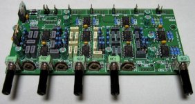
Photo of populated triple version:
An externally hosted image should be here but it was not working when we last tested it.
Attachments
Last edited:
Well, I found a cute little 9-0-9vac transformer, right next to the desk. I believe that it was $5 If used center tap, it makes 13-0-13vdc at the power supply.
It appears that the zenier diode power supply would dispose of voltage that exceeds 12-0-12vdc, leaving the quite simple job of providing it with at least that much.
Is this assumption true?
For reference:
http://www.assemblycraft.com/0903img/psu0.1ucp1smt.GIF
My input voltage is lower. Are these resistor values correct for my application?
If used center tap, it makes 13-0-13vdc at the power supply. It appears that the zenier diode power supply would dispose of voltage that exceeds 12-0-12vdc, leaving the quite simple job of providing it with at least that much.
Is this assumption true?
For reference:
http://www.assemblycraft.com/0903img/psu0.1ucp1smt.GIF
My input voltage is lower. Are these resistor values correct for my application?
Last edited:
hello.
to do some experiments i used a transformer from an old cd player,probably 15VA or so.......:
9,9Vac -0- 9,9Vac secondaries.......
+-12,86Vdc after the rectifier........
and +-12,59Vdc out after the 10 ohm res/z-diode 12V(0,5watt).all volts measured with a load that draws around 6ma (it was a buffer opamp).
c1,c2,c3,c4 ........1000uf/25v.
greetings
Last edited:
Brain farts last night...I think Daniel is on to something that would work better for me.
RCA in to Balanced Line Driver [DRV134] and balanced out to mono preamp board and then balanced out to Rod's Project 125...when the newer boards are ready, of course?
After the balanced line driver do I need the preamp in the middle or could it go straight out to the crossover boards balanced inputs? Depending on gain requirements I guess?
If I get everything in one case it would minimize the amount of XLR connectors required. Power amp modules could also be incorporated either in the same case [getting big or multi-layer, with those bigger power amp transformers and power supplies as seperate power humpty's. DC input to main case for power amps] or a conduit connected daughter case and no XLR or clunky interconnect anywhere! RCA in and speaker driver posts out...lots of them.
2-gang volume pot at the beginning of the chain? I would like the front face plate of the box? to have one volume knob only for both channels. That's a strong requirement for me...
Attachments
Last edited:
I'm in early on the new My Ref C group buy by Udailey for Mauro Pensa's wonderful design and I was thinking of using those modules for at least one of the 3-way speaker driver sections left and right. Those power amp modules require a balanced input. Would it be a logical assumption that the balanced line driver could also be used post-crossover to feed the power amp?
I'm not sure if Rod's Project 125 has balanced outputs?
I'm not sure if Rod's Project 125 has balanced outputs?
Last edited:
hello i am back.i have a new stuff.
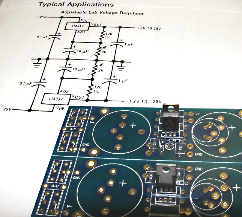
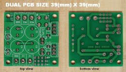
this DUAL power supply is for universal using.although it is a typical application of the fixed regulator chips,i plan everything.i am pretty happy when i got the pcb and have it running
the pcb size is as same as UCPv1 & UCPv2,the module have five output ports.
-zang
this DUAL power supply is for universal using.although it is a typical application of the fixed regulator chips,i plan everything.i am pretty happy when i got the pcb and have it running
the pcb size is as same as UCPv1 & UCPv2,the module have five output ports.
-zang
Attachments
Active regulator in mini?...with up to 3000uf per rail available, or whatever capacitors fit the board?
Simply brilliant!
Those are additional outputs? For a minute there I thought the extra pads on the output traces were for shunting LED's.
Can that be done?
Simply brilliant!
Those are additional outputs? For a minute there I thought the extra pads on the output traces were for shunting LED's.
Can that be done?
Last edited:
Is this the little bug for B1, I assume the bridge rectifier:: Little Bug
...60 cents.
...83 cents from another manufacturer.
both at Digikey.
For this I could probably recycle a transformer from an older dead Philips CD player I have, maybe.
Somehow, I have to wrap my head around the idea of 60 cents vs $1.23 X 8 [$9.84] for MUR86O's. The building of many active speaker systems just became more practical.
...looking closer at the traces the AC in are on diagonal corners. Hmmmm....
So much to learn and experience.
Last edited:
This one's a 2-amp but it appears to have the right pin pattern with AC on diagonal corners. 5mm lead spacing?
79 cents at Mouser \
1.5 amp 200V for 48 cents. With the regulators and diodes this would be a great power supply. Frees up cash for premium capacitors...or not.
79 cents at Mouser \
1.5 amp 200V for 48 cents. With the regulators and diodes this would be a great power supply. Frees up cash for premium capacitors...or not.
Last edited:
Active regulator in mini?...with up to 3000uf per rail available, or whatever capacitors fit the board?
Those are additional outputs? For a minute there I thought the extra pads on the output traces were for shunting LED's.
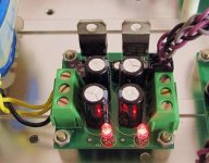
yes,the mini is first considered.
some small kind computer caps 2200uf/16v will fit the board for a purpose of +/-12VDC output,using LM7812/LM7912 regulator.
the extra pads on the output traces were for four 3pins sip header.they are very useful board to board wiring & do some digital kind stuff.
the B1 is a column bridge rectifier,5mm lead spacing.
thanks for the comment about the layout,i am enjoy this thing
zang1.5 amp 200V for 48 cents. With the regulators and diodes this would be a great power supply. Frees up cash for premium capacitors...or not.
i recommand use tantium caps for C5,C6.
i recommand use tantium caps for C5,C6.
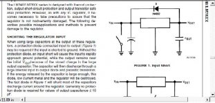
I think this from the National App notes explains the diode and the 10uf output capacitor. For protection against a shorted input to ground. Nice.
Attachments
yes,the mini is first considered.
some small kind computer caps 2200uf/16v will fit the board for a purpose of +/-12VDC output,using LM7812/LM7912 regulator.
the extra pads on the output traces were for four 3pins sip header.they are very useful board to board wiring & do some digital kind stuff.
the B1 is a column bridge rectifier,5mm lead spacing.
thanks for the comment about the layout,i am enjoy this thing
At C1, C2, C3, C4, size can be 1000uF or larger and at 25vdc rating because of rectifying/smoothing task (caps at the rectifier are exposed to more than DC).
After the smoothing task is complete, there is only DC, and then the caps can be 16vdc rated.
- Status
- This old topic is closed. If you want to reopen this topic, contact a moderator using the "Report Post" button.
- Home
- Amplifiers
- Chip Amps
- universal chip pre-amp project