Hi guys, I have a problem on a precision power a600 amplifier.
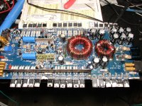
Basically the amp came to me not working, I saw that one bank of transistors had components the other totally different, not having an original schematic to refer to.
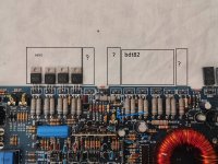
I think the 4 npn bdt 81 and bdt 82 are original (the other bank mounted bd711 and bd712).
I would like to know what original amps it mounted ee above all it did not come to me complete, but transistors were missing.
I enclose the photo of the amplifier by circling the parts not present of which I would like to know the abbreviation in order to install them corettamente on the net I have not found anything about it.
Basically the amp came to me not working, I saw that one bank of transistors had components the other totally different, not having an original schematic to refer to.
I think the 4 npn bdt 81 and bdt 82 are original (the other bank mounted bd711 and bd712).
I would like to know what original amps it mounted ee above all it did not come to me complete, but transistors were missing.
I enclose the photo of the amplifier by circling the parts not present of which I would like to know the abbreviation in order to install them corettamente on the net I have not found anything about it.
Attachments
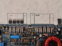

thanks perry, then I saw from the picture that the last transistor (sulvulator side) are different from one channel bdt 81 and of the other bdt82 .
the 2 drivers are 2sa1011 , 2sc 2344.
now sourcing these finals is very difficult for me, I saw as equivalent:
btd81 equivalent 2n6488
btd82 equivalent 2n6491
equivalent for the 2 sa1011, 2 sc2344 on the other hand I have many doubts about it.
the 2 drivers are 2sa1011 , 2sc 2344.
now sourcing these finals is very difficult for me, I saw as equivalent:
btd81 equivalent 2n6488
btd82 equivalent 2n6491
equivalent for the 2 sa1011, 2 sc2344 on the other hand I have many doubts about it.
Today I had 2 minutes to devote to this amplifier.
I installed 1 full bank right output.
Given power supply , no-load draw on the 1.5 amper going up .
no red/orange power led on and no red led in center pcb either.
rail voltage measurements +-40v present on transistor collectors.
connected an ap to output no sound .
dui transistor measurements in operation :
bdt81
base -1.041v
40v collector
emitter -1.5v
bdt82
base -2.022v
collector -40v
emitter -1.55v
power supply set at 14v only one channel installed, at no load starts from 1 amp and quickly rises to 1.5 ah, I noticed that the pnp part bdt 82 heats up much more than the npn part.
the strange thing is that as mentioned before, the red or orange led does not light up even if the pwm is feeding.
the strange thing is that on the bases of the npn and pnp transistors I have negative voltages. 1.040v and 2.022v negative.
And on the emitter output same thing negative value.
the strange thing is that as mentioned before, the red or orange led does not light up even if the pwm is feeding.
the strange thing is that on the bases of the npn and pnp transistors I have negative voltages. 1.040v and 2.022v negative.
And on the emitter output same thing negative value.
Basically , I rotated the bias trimmer to see if the voltage on the transistor base varied , but nothing varies!
I removed the vertical driver board and installed the other channel one, nothing changed.
I shorted the 2 pins in the middle of the drivers (where there is the diode) the absorption dropped.
I removed the vertical driver board and installed the other channel one, nothing changed.
I shorted the 2 pins in the middle of the drivers (where there is the diode) the absorption dropped.
but the thing that doesn't seem normal to me is to have a negative voltage on both the base of the bdt81 and in the btd82, and on the bdt82 it is double as the value of the bdt81, and what is still strange is that by turning the trimmer of the bias this voltage at the ends of the base of the transistors does not vary.
Hi guys , I update you , I replaced the 2 zener diodes cr13 and cr3 as I had no power on the lm833 , now the amp turns on , I verified that the q29, q23 q21 q19 were damaged, I attached the picture of the components, but I can't find them on the net , they are if I'm not mistaken de jfet n, could I adapt others easily available?
Attachments
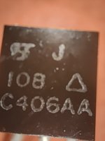
JFETs cause a lot of techs to believe that they're defective.
From gate to source, they should check like a diode.
From drain to source, they should read whatever resistance is given in their datasheet. For this JFET, expect to read approximately 7 ohms, drain to source.
^^^ all of this is with the JFET out of the circuit.
From gate to source, they should check like a diode.
From drain to source, they should read whatever resistance is given in their datasheet. For this JFET, expect to read approximately 7 ohms, drain to source.
^^^ all of this is with the JFET out of the circuit.
- Home
- General Interest
- Car Audio
- Problem Precision Power A600