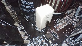
For starters I have an Audiopipe APDLO-16001D which is a dealer line series amp that can only be bought at brick and mortar stores of which there are only 3 of on the east Coast two in Florida and one in Connecticut. I live in NC right in the middle of them. I got lucky and bought it new in box from a guy local to me for $80 (so cheap I felt bad and tried to offer him $100 😂) as of right now replacing it is out of the question (with any amp at the moment for cost reasons) because of cost and distance, I am handy with electrical circuits and soldering so I would like to attempt to repair it myself with either new parts or parts salvageable from other amplifiers/electronics. So burnt up 3 of what Im pretty sure are mossfets, and one of the capacitors, that I can visibly see atleast. I called Audiopipe tech support and found out that it was likely from connecting the subwoofer with the amp already powered up. Something I had never had an issue with before or heard of. But I guess there's always something to learn. Also a few weeks back I could hear something loose inside the amp when I was moving it to its new location when I removed the cover it was a white ceramic box that was supposed to be attached to a post on the board labeled RX1 it had the same one opposite side of the board labeled RX2 still attached and the amp had been and was still playing fine with it disconnected so I removed it, put the cover back on and continued playing the amp with no problems until yesterday when I made the mistake that ended the amp. He told me I could email tech support for a schematic (not knowing what I'm looking at is 90% of the problem at hand, parts availability and money is the other 10%). So a schematic(if anyone happens to have one as Audiopipe has not yet replied) and parts list, potential electronics to find usable parts in and a second set of eyes that know what they are looking at and any other parts that may have damage that can't be seen along with any suggestions as far as what setting as far as volts/ohms/amps etc. and where/what to test with my multimeter for further diagnosis, would be super helpful. Attached are photos of what damage is visible along with an old Memphis 16-ST1000D that I could get some resistors and other common parts from if possible/needed.
TIA
TIA
Attachments
-
 17019001880145391061629270623677.jpg313.8 KB · Views: 194
 -
 IMG_20231206_165458541_HDR.jpg293.2 KB · Views: 203
 -
 IMG_20231206_165527388_HDR.jpg281.1 KB · Views: 205
 -
 IMG_20231206_165517492_HDR.jpg294.3 KB · Views: 196
 -
 IMG_20231206_165547355_HDR.jpg282 KB · Views: 185
 -
 IMG_20231206_165553372_HDR.jpg301.3 KB · Views: 187

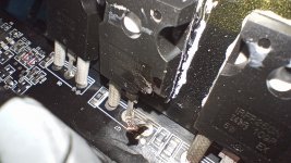
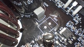
I don't think I've ever seen a TO-247 device blow a lead like that. That took some current. I have seen them explode, but never a blown lead. Nice work! ")
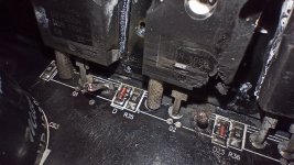
Anyway. Q1 and Q2 are due for replacement ... just in case it isn't obvious. If RX1 is the same as RX2 then RX1 is a vertical 3.3 kΩ resistor. Probably a 5 W type. You can check the dimensions and compare with the data sheet of the replacement resistor. I wouldn't worry about the black snot that runs up RX2. It's probably some glue that got smeared around when the nearby electrolytic capacitor was glued down.
It looks like the MOSFETs are by International Rectifiers. You can still see the part number on the blown devices: IRFP250N. Double-check as some may have a different polarity, hence, different part number. It looks like the IRFP250N been replaced by the IRFP250NPBF. I bet the added PBF stands for lead-free, so the device is the same it just has lead-free solder on the pins. They're about $3 on Mouser: P/N: 942-IRFP250NPBF.
I think the real question is how much else fried in the process and how much molten metal got sprayed in places where you don't want it. I guess you'll find out.
If you have a way of getting the schematic I suggest doing so. It'll definitely help. I also suggest wearing eye protection when you first power it up after repair.
Tom
Anyway. Q1 and Q2 are due for replacement ... just in case it isn't obvious.
If RX1 is the same as RX2 then RX1 is a vertical 3.3 kΩ resistor. Probably a 5 W type. You can check the dimensions and compare with the data sheet of the replacement resistor. I wouldn't worry about the black snot that runs up RX2. It's probably some glue that got smeared around when the nearby electrolytic capacitor was glued down.It looks like the MOSFETs are by International Rectifiers. You can still see the part number on the blown devices: IRFP250N. Double-check as some may have a different polarity, hence, different part number. It looks like the IRFP250N been replaced by the IRFP250NPBF. I bet the added PBF stands for lead-free, so the device is the same it just has lead-free solder on the pins. They're about $3 on Mouser: P/N: 942-IRFP250NPBF.
I think the real question is how much else fried in the process and how much molten metal got sprayed in places where you don't want it. I guess you'll find out.
If you have a way of getting the schematic I suggest doing so. It'll definitely help. I also suggest wearing eye protection when you first power it up after repair.
Tom
I agree. the PBF is just lead free and will work in place of the non-pdf.
I don't know how many parallel outputs there are but all in parallel with failed FETs need to be replaced.
The RX resistors are likely bleeder resistors and don't affect the operation of the amp. They just bleed off the rail caps when the amp is switched off.
The black rubbery substance is a fixative that's used to prevent what happened to the missing RX resistor. It wasn't applied very well. It can remain but the black soot has to be removed.
Attached is a similar diagram.
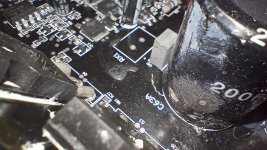
The damage is likely to go back to the optocouplers.
You will have to scrape away any burned material and you need to clean the board with acetone. to confirm that you have it 100% clean.
In the future, please break up the text. One big block makes it much more difficult (for me) to read.
Do you have a scope?
I don't know how many parallel outputs there are but all in parallel with failed FETs need to be replaced.
The RX resistors are likely bleeder resistors and don't affect the operation of the amp. They just bleed off the rail caps when the amp is switched off.
The black rubbery substance is a fixative that's used to prevent what happened to the missing RX resistor. It wasn't applied very well. It can remain but the black soot has to be removed.
Attached is a similar diagram.
The damage is likely to go back to the optocouplers.
You will have to scrape away any burned material and you need to clean the board with acetone. to confirm that you have it 100% clean.
In the future, please break up the text. One big block makes it much more difficult (for me) to read.
Do you have a scope?
Attachments
Last edited:
+1In the future, please break up the text. One big block makes it much more difficult (for me) to read.
Paragraphs were invented for a reason.
If enough current flowed to fry the pins of the devices I wonder if the PCB is still good. I guess you'll find out.
Tom
Thanks wasn't even trying. You should see the results when I am 🤣Wow. That’s an impressive failure.
Smoke is 1000% an understatement. I started the truck( powering up the amplifier) connected the wires and took off.And I thought the recent affairs with smoke coming out of a 5U/400 chassis were impressive.
Did this thing like SMOKE? AsFredJim noticed, that is truly "impressive"... as it is, I think this is an understatement.
Being rushed was where the mistake was made. And I made it about a mile from my house before I had picked a song and noticed no sound coming from the woofer then almost immediately got the stomach turning smell of cooked electronics.
Before I could pull onto the shoulder and stop the back half of the 4runner was full of smoke so I rolled all the windows down and ran to the hatch to lay eyes on what was happening instead of going under the hood to trip the breaker. But hindsight is 20/20.
By the time I had the hatch all the way open it was actually blowing smoke like a fog machine. And then before I could think of what I was supposed to do next (again should have done first) I watched it go from smoke to a fireball inside the amp that burned with the intensity of a torch and lit up the insides enough i coud see the guts through the vents and bright light from around the gain, low/highpass filter, etc knobs. For a solid 2 seconds.
I immediately grabbed the 1/0 awg power wire, snatched it out (made sure it wasn't resting on anything it could short out on) and ran up front and manually tripped the breaker. Accepted defeat and continued on my way with an extremely unflattering amount of mids & highs and zero lows.
Hi Tom,
Having devices fail like that is not uncommon in car power amps, or large high power PA amps. Makes a mess though. I've seen the tops of TO-204 cases burned through, and also a metal shield above that. Now, that is impressive! It's also impressive the metal tops remained attached!
Perry's right. Clean, clean, clean. See what's left. Check everything in the current path, and replace one stage before the last failed part as well. Nothing was happy there! lol!
lol!
I can't take credit for that, and didn't see it happen. Reportedly it made one heck of a boom sound.
Plug a Carver PM 1.5 into 550 VAC and bad shite is bound to happen. Yeah, that amp was barely worth repair, got a donor power transformer from another dead thing. I think I replaced one entire amp PCB also.
The plasma would have exited the bottom under the amp. Too bad no one saw it in all its glory, probably just an unearthly flash! lol! I wonder if the amp lifted off?
Fuses are thermal things. They take time to heat up and open. Obviously things happen very quickly when you have extreme circumstances.
Also, what some folks do not realise is that fuses have a voltage rating. This is the maximum voltage the fuse is tested and rated to interrupt. Voltages greatly in excess of this may well continue to arc. This causes very interesting damage to occur inside the fuse holder. The normal 3AG size cartridge fuse is rated for 250 VAC maximum, some lower.
I was always amazed when I found 32 VDC automotive fuses installed in primary AC mains locations. Are people really that stupid???? Rhetorical question.
175 amp breaker switch, thinking about going back to a fuse between it and the battery to double up on protection thoDo u not have a fuse in ur power line? Shoulda popped I would think
In car audio, you normally have a large value fuse near the battery to protect the B+ feed (cable), then the amplifier would have one as well. I had a distribution block with fuses for each item on the board where they were mounted. That's just good practice. Your amplifier should have had an internal fuse.
I have a distribution block with fused outputs for accessories like interior lighting, extra power outlets, ditch lights etc. the old amplifiers 4 awg power cable originally had a 100amp fuse about 12 inches from the battery and two 30amp fuses in the amp. When I upgraded amps (roughly double the continuous output I cleaned existing body and motor grounding points added a chassis to battery ground and moved up to a 1/0 awg power cable larger fuses weren't readily available near me however the 175 amp breaker was and should have been plenty for new amp (which also has 2 40 amp fuses) and cable and correct me if I'm wrong should function the exact same as an equivalently rated fuse aside from if it did trip I would just have to reset it as opposed to buying another fuse or ordering online and waiting for it? That was my thinking at least.
- Home
- General Interest
- Car Audio
- I ***** up