I saw this amp on sale together with some Dali speakers for a good price, so I searched for the service manual online and liked the topology. I've wanted to build something similar, 3EF made for high current, for some time, and here it was using fast transistors etc. and a lot cheaper than starting from scratch The general design is nice too I think (ok maybe not the front plate), with channels fully separated, only a common transformer (with separate secondaries).
There was a slight hum, and I later found bad electrolytic caps in the low voltage supplies, probably because they are constantly powered in standby. Main PS caps were fine, since they are not powered in standby. I listened to it for a couple of hours, and I liked the sound, except bass that was a bit loose. I did a quick distortion measurement, it was 3rd dominant, and between -90 to -100dB at 1kHz depending on load and power (not close to clipping). With multitone, the 'distortion floor' looked flat through the audio band. Not a lot of loop gain (32dB), but it seems to be flat through the audio band.
So, plan is to make some mods to this amp, and just in case somebody in interested, I thought I would share the sim. I could not find C6 (in sim) on the boards, and I can't really see why it would be needed (quite a large value too). Had to substitute some (video)transistors that I could not find models for, so stability sim is not very reliable, but I use it as a reference point for what was stable.
My plan is to do an AKSA-inspired mod to improve bass, but keep the relaxed sound in the rest of the range. I have done that to a couple of amps now with (IMHO) good results. Will see how it ends up. Amp is in pieces as it is now, and will only come together after I received some parts.
Attachments
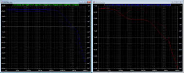
Main change is increased front end gain and adding a nested feedback from the VAS. I increased loop gain by replacing the LTP degen resistors (180 to 1ohm), and the compensation cap C4 was increased to 5.6p to compensate (a little bit high, but safe). Square wave is rounded in the corners. Nested feedback is in parallel with C4, consisting of 0.68n & 860k in series. The idea is to increase global loop gain for bass, and keep it abt the same as before for mid/treble. Thus firming up bass and keeping the same 'sweet' character of the mid/treble as the amp had before. All credits for this to Hugh (AKSA). There are for sure different opinions on this approach, but that is up to every man do decide for himself. It works for me.
I also bypassed a muting stage, makes a small click now when switching between tone controls and 'direct'. Not sure that was worth doing.. I always run direct anyway, and there is one opamp, a shunting transistor and two caps per channel less for the signal to pass, so it made me feel better")
Replaced a lot of caps in the low voltage PS that were starting to dry out.
Adjusted bias while monitoring distortion FFT. Looked best just below the bias specified in the manual. I was not only looking at absolute level, but the harmonic content.
Distortion measures essentially the same as before the mod, but would probably be lower in the bass, but I did not compare that.
This amp is very insensitive to low impedances, switching between 8 & 4 ohms load the distortion changes very little compared to many other amps I measured. A lot of current gain in the topology does that I guess.
I also bypassed a muting stage, makes a small click now when switching between tone controls and 'direct'. Not sure that was worth doing.. I always run direct anyway, and there is one opamp, a shunting transistor and two caps per channel less for the signal to pass, so it made me feel better
Replaced a lot of caps in the low voltage PS that were starting to dry out.
Adjusted bias while monitoring distortion FFT. Looked best just below the bias specified in the manual. I was not only looking at absolute level, but the harmonic content.
Distortion measures essentially the same as before the mod, but would probably be lower in the bass, but I did not compare that.
This amp is very insensitive to low impedances, switching between 8 & 4 ohms load the distortion changes very little compared to many other amps I measured. A lot of current gain in the topology does that I guess.
For muting I have seen good and bad in old Japanese. Better ones adding less THD were in Nakamichi for example. Using 25V Vebo high reverse Hfe Toshiba with threshold diodes. I tried to run your sim file by the way but I get an error message "missing schematic(s) of the hierarchy: lg_single".
Ok, I must have forgotten that.. Unzip this to the same folder, or you can remove LGS from the sim if you're not running loop gain sims.
Yeah, removing the muting stage was just based on a gut feeling.. I felt the muting was not really needed. There is separate muting via the input stage CCS, output relays, PS relays etc, so no thumps or clicks in general, just when switching direct/tone, and it's not loud.
Yeah, removing the muting stage was just based on a gut feeling.. I felt the muting was not really needed. There is separate muting via the input stage CCS, output relays, PS relays etc, so no thumps or clicks in general, just when switching direct/tone, and it's not loud.
Attachments
Did you save any FFT screenshots for us to see?Adjusted bias while monitoring distortion FFT. Looked best just below the bias specified in the manual. I was not only looking at absolute level, but the harmonic content.
Distortion measures essentially the same as before the mod, but would probably be lower in the bass, but I did not compare that.
This amp is very insensitive to low impedances, switching between 8 & 4 ohms load the distortion changes very little compared to many other amps I measured. A lot of current gain in the topology does that I guess.
Ok, I must have forgotten that.. Unzip this to the same folder, or you can remove LGS from the sim if you're not running loop gain sims.
Yeah, removing the muting stage was just based on a gut feeling.. I felt the muting was not really needed. There is separate muting via the input stage CCS, output relays, PS relays etc, so no thumps or clicks in general, just when switching direct/tone, and it's not loud.
 Now it runs. I see that amp's service manual now, I quickly spotted a Q305 2SC3327 Toshiba switch that's also very good for muting. Should have used more of this instead of KSR1003s.
No.. I did not think there would be any interest in it, so I did not document it..
Going too low on bias gave an array of falling high order harmonics (as usual on AB amps) with odds dominating, and going too high the 3rd would increase again, and some higher orders would again become visible above the noise. 3rd is dominant on this amp, but with the setting I did, I tried to minimize it's dominance. The set voltage (over emitter resistors) was not exactly the same on both channels, from memory I ended up with 25 & 27mV, measured on the connector for bias adjustment, so only one pair measured per channel. I think manual stated 30mV.
I think this is actually the first time I used a setting lower than specified in the manual, usually (on cheap amps) I found that increasing bias over the manual has reduced distortion.
Last edited:
The R & C values are a matter of taste, possibly influenced by the speakers used too, maybe even the room.. I would say 0.68-1n is usable here, and resistor value maybe 680k-1M. Some might even prefer it without the nested feedback, with increased global loop gain and more 'detail' to the sound. It should be stable either way.
I have also seen increasing third harmonic profile in some Class A push pull when the bias gets increased too much although THD drops a little as a whole. Matter of deciding a sweet spot bias I guess.No.. I did not think there would be any interest in it, so I did not document it..
Going too low on bias gave an array of falling high order harmonics (as usual on AB amps) with odds dominating, and going too high the 3rd would increase again, and some higher orders would again become visible above the noise. 3rd is dominant on this amp, but with the setting I did, I tried to minimize it's dominance. The set voltage (over emitter resistors) was not exactly the same on both channels, from memory I ended up with 25 & 27mV, measured on the connector for bias adjustment, so only one pair measured per channel. I think manual stated 30mV.
I think this is actually the first time I used a setting lower than specified in the manual, usually (on cheap amps) I found that increasing bias over the manual has reduced distortion.
Now we are good.Try checking these settings:
Attachments
Good!
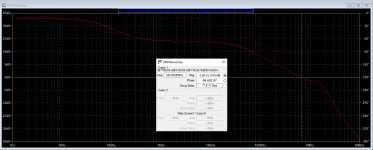
Just remember that the stability sim is not accurate for stability since some models are not correct. I used the 0dB 'crossing' (unity gain is the correct term I think) as a measure to increase the capacitance of the compensation cap after the mod. Compared it to the standard setup and made sure it was not crossing higher in frequency after the mod.
Just remember that the stability sim is not accurate for stability since some models are not correct. I used the 0dB 'crossing' (unity gain is the correct term I think) as a measure to increase the capacitance of the compensation cap after the mod. Compared it to the standard setup and made sure it was not crossing higher in frequency after the mod.
- Home
- Amplifiers
- Solid State
- HK670 integrated amp sim, mods etc