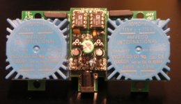
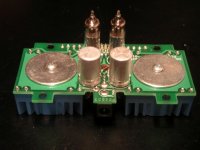
I've taken a look at the iMPAMP web page - it's a cute design. Here is my reverse-engineering summary:
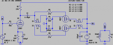
Amplifier topology is a single stage push-pull using 6021W sub-mini tube. That tube has 0.7W anode dissipation rating, which means that it runs in Class B to get 1W output. Bias for PP pair is done with a single blue LED. External 12V/1A PSU feeds two 6021 heaters in series, and HT is stepped up inside by a pair of AMVECO 70000K 1.6W toroids connected in reverse. Rectifier is obviously solid state. The only thing which is not quite clear is how phase splitting is done in a front-end...
Amplifier topology is a single stage push-pull using 6021W sub-mini tube. That tube has 0.7W anode dissipation rating, which means that it runs in Class B to get 1W output. Bias for PP pair is done with a single blue LED. External 12V/1A PSU feeds two 6021 heaters in series, and HT is stepped up inside by a pair of AMVECO 70000K 1.6W toroids connected in reverse. Rectifier is obviously solid state. The only thing which is not quite clear is how phase splitting is done in a front-end...
Cool amp!
Fostex FE207E has a high sensitivity, 95db/W you`ll need it with just a one watt amp.
5902 subminiature pentode has a max anode dissipation of 4W, could make a cool little single ended 1W spud-amp...
Oh no, I got a couple of them in my drawer, juuuuust what I needed now, another project...
Regards,
Peter
Andrei,
You're right !
Here what I found to complete the reverse-engineering of the ImpAmp:
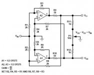
Two OP275 phase-splitter like this circuit (see pic)
(Personnaly I prefered the DRV134 for phase splitting)
Transformer: Fender W022913 (125A10B)
PART# 022913
MOUNTING 2 13/16"
HEIGHT 2"
LENGTH 2 5/16"
WIDTH 2"
WATTS 12
PRIMARY 8500 CT
SEC 8
So nothing missing to build a ImpAmp clone !?
Let's build the YinYamp !
You're right !
Here what I found to complete the reverse-engineering of the ImpAmp:
Two OP275 phase-splitter like this circuit (see pic)
(Personnaly I prefered the DRV134 for phase splitting)
Transformer: Fender W022913 (125A10B)
PART# 022913
MOUNTING 2 13/16"
HEIGHT 2"
LENGTH 2 5/16"
WIDTH 2"
WATTS 12
PRIMARY 8500 CT
SEC 8
So nothing missing to build a ImpAmp clone !?
Let's build the YinYamp !
Attachments
I built a small 1Wpc SE 60FX5 headphone amp. 1 tube per channel!
It sounded pretty good after some tweaking,but all the 60FX5 tubes I could find were pretty microphonic. I dunno if they're all like that,or if it was just the ones I got.
I'm sure there are similar tubes you could use that might be better in that respect.
The schematic I based the amp on was from an RCA sheet,I think it was used as an X-tal-pickup phono amp ?
Might make a sweet little guitar amp,that won't wake the neighborhood.
It sounded pretty good after some tweaking,but all the 60FX5 tubes I could find were pretty microphonic.
I dunno if they're all like that,or if it was just the ones I got.I'm sure there are similar tubes you could use that might be better in that respect.
The schematic I based the amp on was from an RCA sheet,I think it was used as an X-tal-pickup phono amp ?
Might make a sweet little guitar amp,that won't wake the neighborhood.
autoformer is way cooler...
Andrei,
Your 6SN7-6BX7 push-pull amp design in this thread is really cool !
a tiny Tamura MET-09 in autoformer mode at input !Y!E!A!H!
Could you suggest me a turn ratio for the toroidal output transformer ?
I have some Amveco 62070 in my parts bin but I don't have an inductance meter to mesure it for ~ 64mH ?
I want to test and listen this great idea.
Thanks! Now I'll have to build this thing to see if it works .
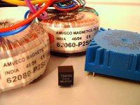
Actually, I designed for Amveco 62070 (parallel secondaries) as output transformer. I measured one with LCR meter, and the measured values looked really good. Leakage inductance is small, so high frequency extension is not going to be a problem, which was a concern since it is never documented for power transformers (you could guess the primary inductance from idle current spec). I can look up the exact numbers if you are interested.
.Actually, I designed for Amveco 62070 (parallel secondaries) as output transformer. I measured one with LCR meter, and the measured values looked really good. Leakage inductance is small, so high frequency extension is not going to be a problem, which was a concern since it is never documented for power transformers (you could guess the primary inductance from idle current spec). I can look up the exact numbers if you are interested.
6SN7-6BX7 push-pull amp design
Hi Andrei,
I've some 7v + 7v toroid from Amveco to try with your design.
If the primary impedance will be the ratio squared x the secondary impedance.
Ratio: 115 / 7 = 16.5
Primary impedance: 16.5 x 16.5 x 8 = 2178 ohm (seem to be OK with this low Rp TV triode)
Next I've to found some 6BX7GT and I'll be ready to test it...
Sylvain
Attachments
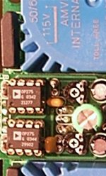
wow, you guys are a trip! 8^) remember that the OP275 opamps are mounted on a daughter board and there are components underneath them as well. there are no capacitors in the audio path (all DC-coupled) except two tiny ones in the negative feedback loop of the input to deter RF oscillation. good luck! 8^)
- Status
- This old topic is closed. If you want to reopen this topic, contact a moderator using the "Report Post" button.
- Home
- Amplifiers
- Tubes / Valves
- DIY something like iMPAMP??