Hello. marinho send me a complete set of documents by email neoton_@mail.ru.
A good audio OpAmp would be the best solution, but it must be as precise as possible at the offset value.Can the OPA2277 chip be replaced with an OPA2227?
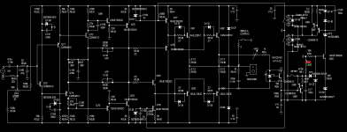
This is a schematic of the Dart. double transistor with protection only simulated by me on microcap12
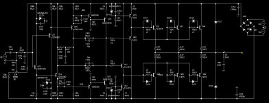
And this with triple. Note that the driver bias must be increased by double
And this with triple. Note that the driver bias must be increased by double
Attachments
Last edited:
I was thinking about multiple outputs the other day, -maybe it would be possible to run multiple output pairs with just the base resistors and skip the emitter resistors because they increase output impedance? The base resistor 'mirrors/emulates' an emitter resistor times the hfe of the transistor, so matching them for Vbe and hfe could make it feasible? Could even be possible to do some fine tuning on the base resistors to even out the current sharing between outputs?
An example is the 27 ohm base resistors act as 0.27ohm emitter resistors if the hfe is 100.
An example is the 27 ohm base resistors act as 0.27ohm emitter resistors if the hfe is 100.
With emitter resistors only the change in Vbe affects things, but with base resistors the change in current gain and the change in Vbe work together for even more asymmetry (gain rises with temperature). Its the dynamic imbalance that causes problems, not the static imbalance - no amount of static matching will stop dynamic imbalance from developing if the thermal feedback is too weak. And in general its asking for trouble to design circuits that expect stable values of hfe - hfe isn't well characterized and varies with device, temperature, current, collector voltage and history - its like expecting an electrolytic capacitor to have tight tolerance...
Yes, it's a odd workaround, but I guess bias stability is not critical, since it's very 'overbiased' compared to a standard AB output stage. Variations in the bias current will just vary the class A operation area a bit. The output stage is not exactly following the mainstream design ") Seems priorities have been elsewhere, seems it's been 'bodged' together, and still received some nice reviews, that makes me curious..
Seems priorities have been elsewhere, seems it's been 'bodged' together, and still received some nice reviews, that makes me curious..
Seems priorities have been elsewhere, seems it's been 'bodged' together, and still received some nice reviews, that makes me curious..I have finished one board and played around with it a bit on the bench. What I found out so far:
-Scope test look fine, square wave is super clean, and clipping looks ok too.
-Very sensitive DC offset. I'm running it on bench supply, and as soon as I touch one of the rail voltage setting s bit, the DC offset runs away. After adjusting it with a warmed up amp, it's more than 100mV off when starting cold. All the small signal transistors are thermally connected glued to a small alu-piece and copper tape around them.
-Idle current is actually pretty stable, much better than I initially thought.
-Diodes don't seem to matter as much as I thought for distortion. Only on high levels/currents do they give some negative effects in measurements.
-Distortion is pretty good on low levels as long as the output stage is in class A. Only H2 and H3 visible, and they are about -70dB
-When it's cranked up a bit or with a 4ohm load, the distortion goes up a lot, and has a wide spectrum of overtones, distortion level maybe 40-50dB below signal.
-Adjusting the base resistors for the outputs seems like a feasible way to adjust idle current, even if the effect is less than I thought. Halving the resistance (22ohm in parallel with the original resistors) increased the idle current abt 100mA. I guess there is a Vbe compensation from the drivers. Decreasing the resistance also (in sim) decreases output impedance.
-I found that 'balancing' the base resistors can reduce distortion and modify the harmonic profile. When they are 'balanced' H2 and H4 goes down significantly (up to 10-20dB). Also some of the higher harmonics are affected, mostly even harmonics. I guess the hfe-diff between NPN and PNP are balanced out with base resistor tuning. In my case adding a 100ohm trimmer in parallel with the NPN base resistor allowed me to balance it out. If this is better or even audible is another matter.
Setup:
Double 25V bench supplies connected in series, so 25V rails. Output transistors are NJW0281/0302 because the originals were out of stock at Mouser, From memory the data is basically the same except dissipation/current and Cob that are a bit lower for the NJW devices. I use ARTA and Scarlett 2i2 for distortion measurements.
Transistor availability is baa-ad and I'm looking forward to populate couple pcb's more with different flavour resistors.
What do you say using Onsemi 2SA1943/2SC5200 (O-variant) in NHB-108? They seem direct replacement to MJL1302A/MJL3281A but 150w vs 200w ?
What do you say using Onsemi 2SA1943/2SC5200 (O-variant) in NHB-108? They seem direct replacement to MJL1302A/MJL3281A but 150w vs 200w ?
Last edited:
I think it is most to do with dissipation and maybe hfe and Vbe. Since there is no feedback from the outputs, there should not be any issues with oscillation etc. Linearity will of course influence the distortion too, since there is no feedback to correct it. I think the NJW's are the closest you can get. I did not even know that On made the 1943/5200, I thought they were Toshibas or Sankens. Anyway, I guess they should work well too.
I think the critical thing it comes down to what rail voltages you have, and how much heat they have to dissipate. The larger cases are better at dissipating heat. Make sure you have good cooling and good heat transfer from case to heat sink. Maybe some of those aluminum oxide 'pads' would be preferred: https://se.rs-online.com/web/p/thermal-pads/2182609
I think the critical thing it comes down to what rail voltages you have, and how much heat they have to dissipate. The larger cases are better at dissipating heat. Make sure you have good cooling and good heat transfer from case to heat sink. Maybe some of those aluminum oxide 'pads' would be preferred: https://se.rs-online.com/web/p/thermal-pads/2182609
I did some sims of the amp, and found something that I don't think has been discussed before. It seems the PSRR of the amp is really poor at LF with the 6uF input cap. Basically what this means is that if the rails sag a little bit, it translates into the output, and bass is poor. If the rails are super stable with mega caps, there will be very little rail sag even at LF, but all caps have rising impedance with decreasing frequency..
Here are some sims, first with the 6u input cap:

And 20u:

And finally 100u

This is simulated with 1V ripple on the positive rail only. The effect is cancelled if both rails sag at the same time, but they never do, they always alternate depending on if the amp is drawing from the positive or negative rail.
In my mind 20uF looks like absolute minimum, but more is better.
Source impedance was set to 200 Ohm, but that does not seem critical.
Here are some sims, first with the 6u input cap:
And 20u:
And finally 100u
This is simulated with 1V ripple on the positive rail only. The effect is cancelled if both rails sag at the same time, but they never do, they always alternate depending on if the amp is drawing from the positive or negative rail.
In my mind 20uF looks like absolute minimum, but more is better.
Source impedance was set to 200 Ohm, but that does not seem critical.
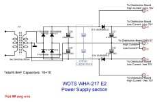
You are right, This happens even in my variant WHA-217 E2 (around post #2107), for this reason, I used 10x6.8mF capacitors per rail/channel and decoupled the VAS from drivers/buffer using a diode per rail, trying to synthesize a sort of stabilizer for the VAS, and it seems to work. Somewhere in an old post of mine, there should be an analysis of the behavior of the diodes setting the quiescent current.
Attachments
Sorry, I must have missed that. I spent a lot of time going through the thread, and there is a lot of discussion about other amps/variants too, so I did not read much about those, but only tried to focus on the NHB 108.
I simulated separate supplies for the front end and for PS ripple I get 72dB. With common rails I get 57dB.
For sagging rail I get 40dB with common rails, and again 72dB with separate front end supply.
I think a cap-multiplier for the front end would be a more elegant solution (cheaper and takes less space), but separate front end supply is definitely a winner also for the NHB 108!
Good to know, I might have to do something about that if I like the amp.
I don't think the gigantic PS cap banks are needed if the input caps are increased or in your case with separate front end supply. I did some output impedance sims with 15000u per rail & channel, and that seems to be enough with the lager input cap to keep the output impedance at a constant 170mOhm to abt 10Hz.
Actually, I think 170mOhm sounds pretty ok for a NGFB amp, I have another NGFB experiment of my own using high bias CFP output, and it sims at 160mOhm output impedance. That one still sounds 'ok' in the bass driving 4 Ohm 3-ways with 8" woofers, -a bit sloppy but not a disaster.
I work only on projects with no feedback but local.
The WHA-217 E2, made on the NHB-108 base, was my last experience with N/P PP pairs. It only misses the feedback from its main output, but has (must use) feedback surrounding the VAS, which is against my wish.
It was an exciting challenge with myself, but I will no longer put my effort into that topology.
Since I discovered the Circlotron Class A circuitry I will continue this way.
My first (and last, by now) Circlotron was the WHA-53 posted here:
https://www.diyaudio.com/community/...clotron-class-a-hybrid-main-amplifier.396135/
Nobody dared to post any comment about it. It far overperforms any amp I came to listen to, and it is very close to a tube with no feedback OTL amp using some pairs of 6C33C, which was my best experience.
I have some other running projects about thrilling preamps (or boring postamps, like someone here wearing sunglasses likes to name them) and, at the very least, an E2 version trying to assemble the WHA-53 in 2 cabinets, not in 4.
You are far better skilled than me and have a deep knowledge; you should continue this way. I'm sure you will enjoy it at least as I enjoyed going across this project. Perhaps you will find a way to eliminate the diodes that allow a low quiescent current to the Diamond Buffer but generate distortion in their transition zone. The 217 is in my wife's set; she uses it daily.
I don't have deep knowledge I'm not much of a designer, just a tinkerer, so I like to try stuff and modify it to make it 'better'. Your projects seem far more advanced
It runs fine without the diodes in my bench tests, just loses a little bit of voltage swing at high currents. I think the base resistance could be decreased, to maybe get a higher bias and lower output impedance. In my case I will be running on 30V rails, so there should be some margin to raise the bias current even with the smaller output devices. I might change some resistor values to bring the currents back up in the front end too. I think there was some mention about selectable rail voltages on the original amp depending on speaker impedance? Does anybody know what they were? I have only seen 55V rails mentioned in some schematics.
I'm not much of a designer, just a tinkerer, so I like to try stuff and modify it to make it 'better'. Your projects seem far more advanced It runs fine without the diodes in my bench tests, just loses a little bit of voltage swing at high currents. I think the base resistance could be decreased, to maybe get a higher bias and lower output impedance. In my case I will be running on 30V rails, so there should be some margin to raise the bias current even with the smaller output devices. I might change some resistor values to bring the currents back up in the front end too. I think there was some mention about selectable rail voltages on the original amp depending on speaker impedance? Does anybody know what they were? I have only seen 55V rails mentioned in some schematics.
I participated in this thread reading almost it whole, but never encountered a voltage selector. I know in the original it is present.
Look here
https://www.audiodesignguide.com/Ibridone/index7.html
its designer, Ciuffoli, is a good one, very experienced, and never used diodes in his diamond buffer amplifiers. He also doesn't use any xVbe, probably relying on the 0.47Ohm REs effect, beyond the thermal coupling drivers/final pairs. Without REs it is easy to run into a thermal avalanche.
0.47Ohm, according to Douglas Self, is a huge value for an RE.
In my WHA-217 I used 0.1Ohm as REs and used a Sziklai xVbe, even because I added one more stage. However, the xVbe is sensitive to the fluctuations of the power rails.
There are 3 items to consider:
REs;
Diodes;
xVbe
Each of them has collaterals. The diodes are the worst, followed by the xVbe and the REs are the best solution.
In a diamond buffer, you should choose at least one of them, and nobody wants to use an xVbe.
So the REs seem to be a forced solution.
But if you have +/-30V rails, I'm positive you can at least try to eliminate the diodes calculating resistor values both on the bases of the final pairs and in the two CCS (117mA original, if I remember), to have a suitable quiescent current without transforming the amp into a heather. Try to rely only on the thermal coupling drivers/final pairs and check the temperature.
The absence of the REs could be a foundation point of the NHB-108 if a very low bias was set. Having a high bias the damage is done, so you are entitled to use the REs.
First sound today. I made a 'plank amp' for testing, minek here on the forum made it an art, but this is not a beauty, just a way to connect everything and test it.

The transformer has dual secondaries, so it is basically dual mono, but sharing the same primary winding. Cap banks are abt 4x16mF, cooling is more than sufficient for the 30V rails,
I have 50Hz hum, and it seems to be related to supply ripple, not ground loop, but I need to check it more still. Not a lot of harmonics it seems, but mostly 50Hz. I quickly measured between rails with the voltmeter on AC, and got a 130mV reading. DC offset seemed ok too.
I listened to some music on my 'garage speakers' which are decent sounding 3-way Yamaha's going down to 4ohms in the bass.
As expected, I was not impressed with the bass control, but mids and treble sounded pretty good. I would say 'airy' mids and treble. Sounds a bit like a tube amp (I have very limited experience with them though), both the good and bad I guess. This was without the diodes mounted.
I need to play around with it a bit, diodes, base resistors etc. Need less hum and, if possible, better bass control.
Any thoughts on changing the 'driver CCS' zeners and resistors to get the output swing closer to the rails, but keeping the current the same? As it is now, it clips abt 5V below rail voltage. Seems like a 'free lunch' but usually there is a catch.
http://www.dartzeel.com/Pages_F/NHB108_1.html
http://www.dartzeel.com/PDF_Files/AudioManuFR.pdf
http://jipihorn.free.fr/Brevets/WO03043185-FR.pdf
http://perso.wanadoo.fr/francis.audio2/C14_Dartzeel_r4.gif
Performances in simulation (second amp):
http://perso.wanadoo.fr/francis.audio2/Concours_Conception_Ampli_part2.doc
Why does their preamplifier have separate coax digital inputs for left and right? I thought the digital bit stream carries ALL channels.
https://dartzeel.com/nhb-18ns/
- Home
- Amplifiers
- Solid State
- Dartzeel amp schematic - build this?